
Mino The Ai Chatbot
Platforms
Categories
Build a Voice-Controlled AI Assistant with ESP32
- Most AI demos today can talk really well, but they can’t do real work.
- In this project, I’ll show you how to build a voice-controlled AI assistant using an ESP32 and Xiaozhi that can safely control real hardware and software automations. This assistant doesn’t just chat; it turns lights ON and OFF, reads sensor data, and even creates and fetches meetings from Google Calendar.
- The key idea behind this project is Model Context Protocol (MCP). MCP acts as a bridge between an AI model and physical systems, allowing the AI to call predefined tools using structured data instead of guessing commands.
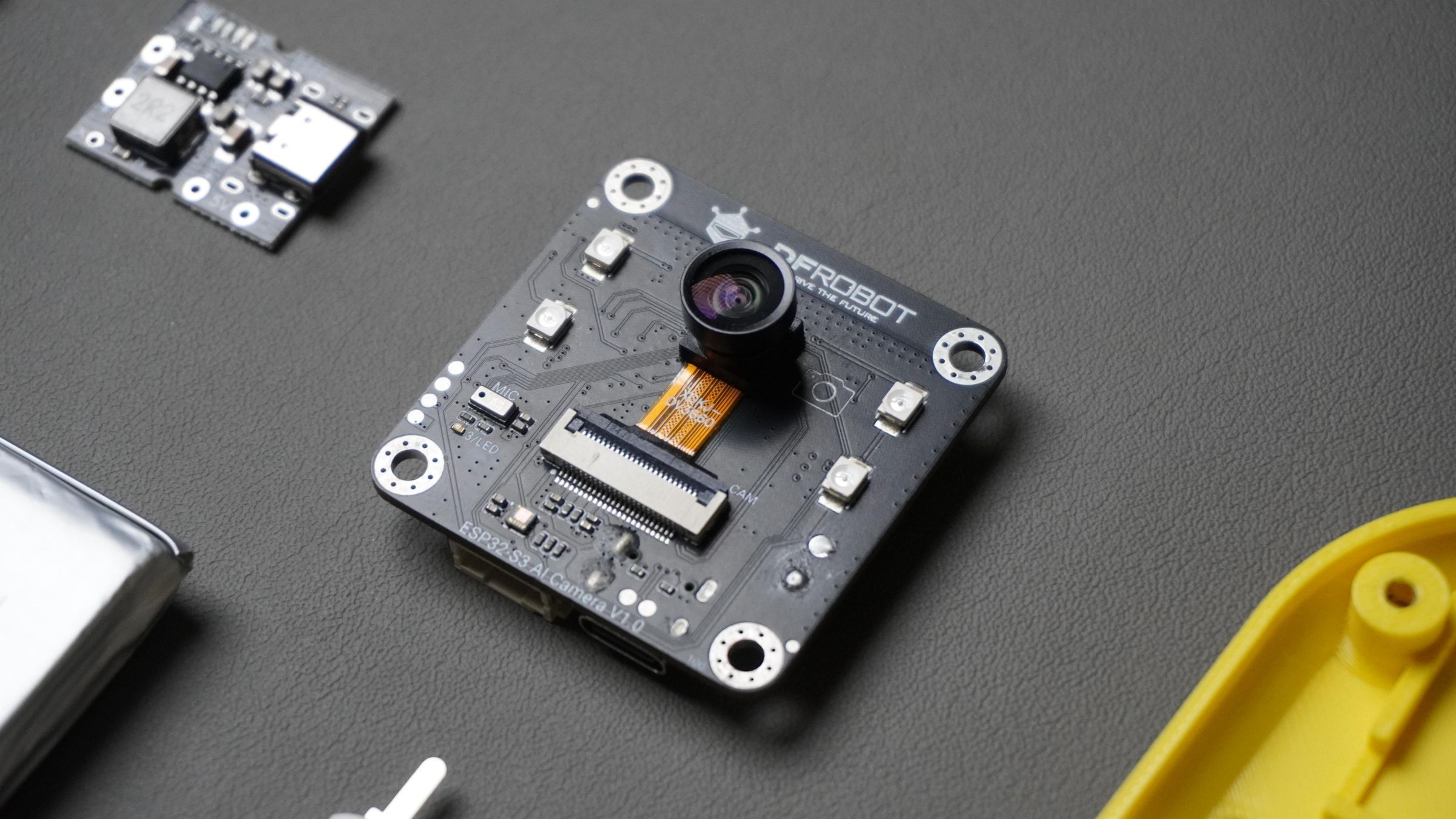
- Using the DFRobot ESP32-S3 AI Cam, we combine voice input, AI decision-making, and real execution on an embedded device. The result is a reliable, predictable, and secure AI assistant that actually works in the real world.
- This guide walks you through the complete process, from hardware setup and enclosure design to MCP tools and real-world automation.
Supplies
Hardware List
Additional Components
- 1 x FireBeetle 2 ESP32 S3
- 1 x DHT11
- 1 x Beetle ESP32 C3
- 1 x 10A Relay
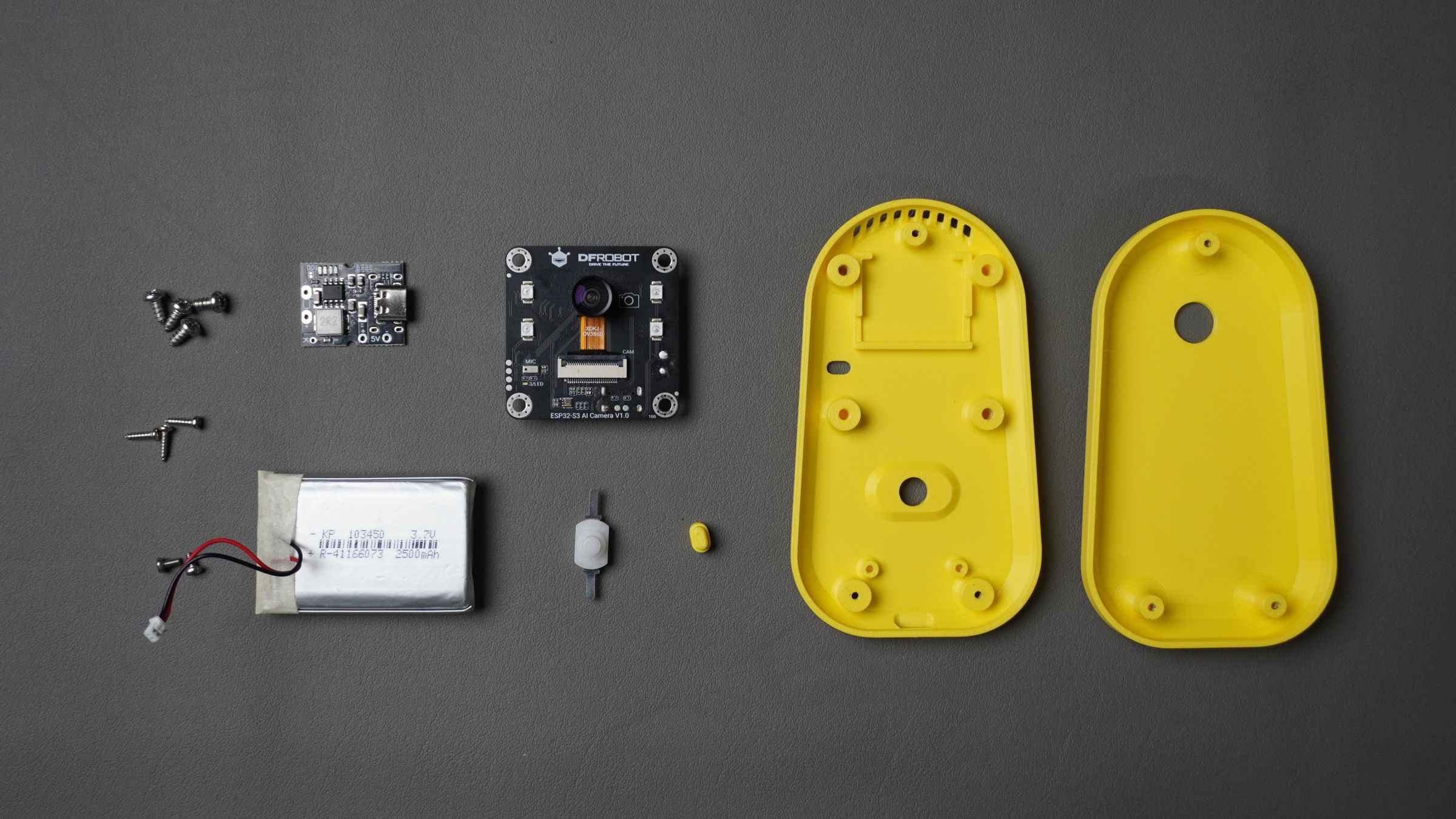
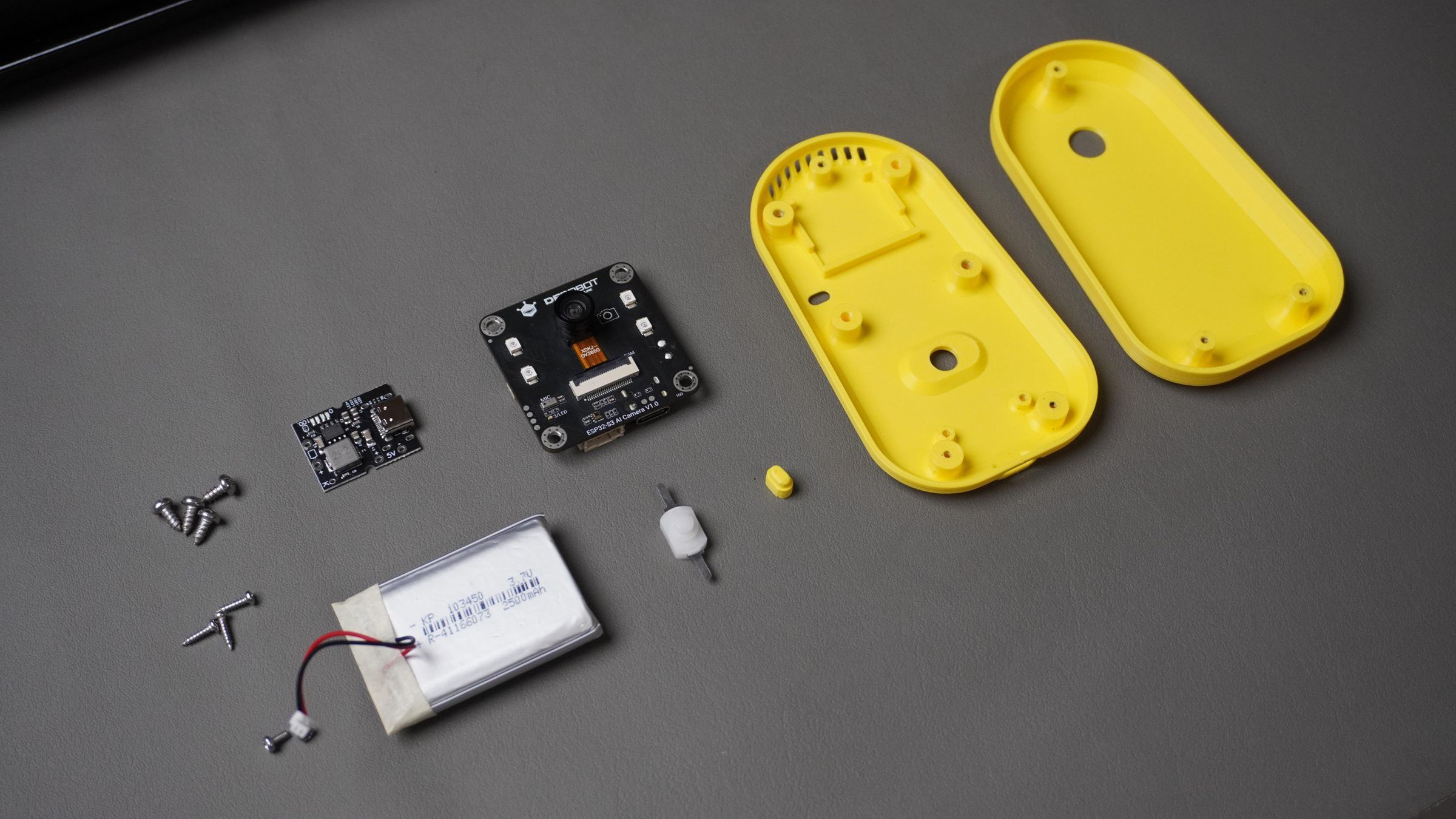
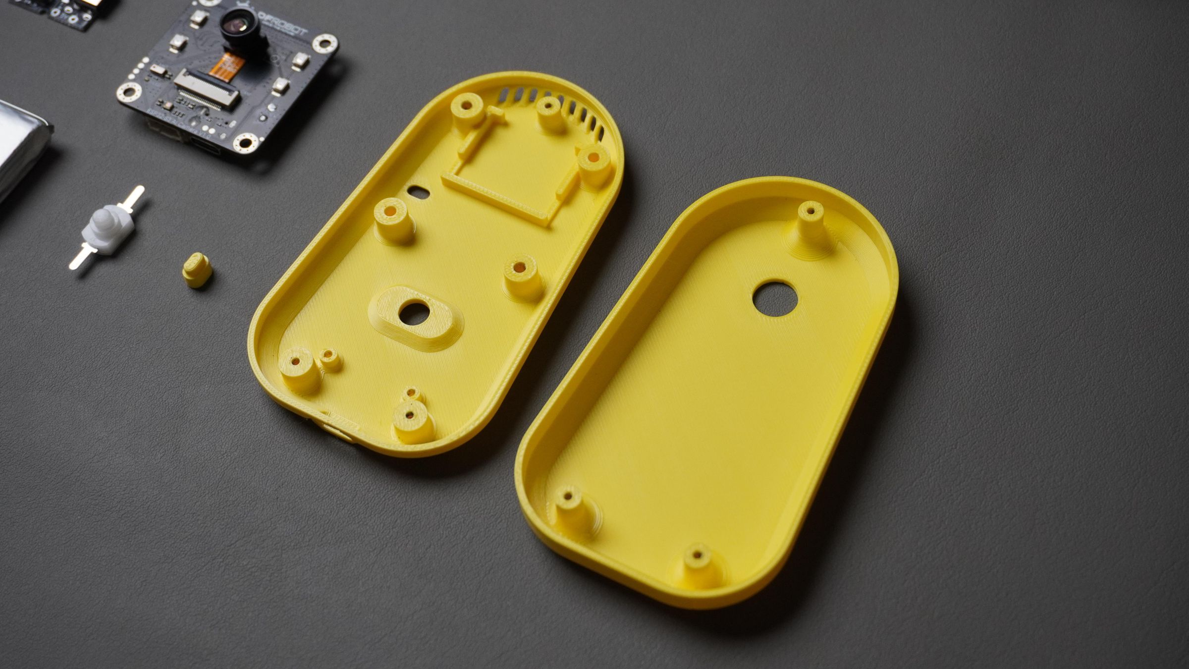
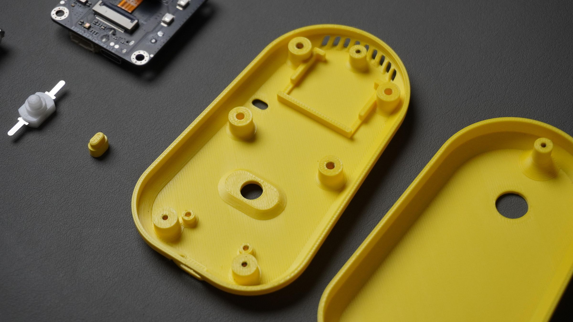
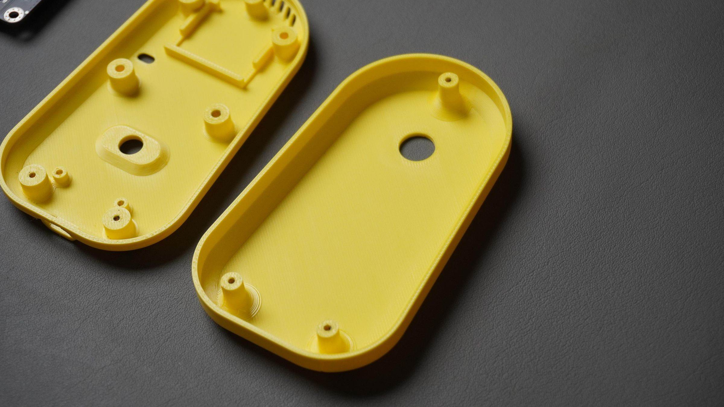
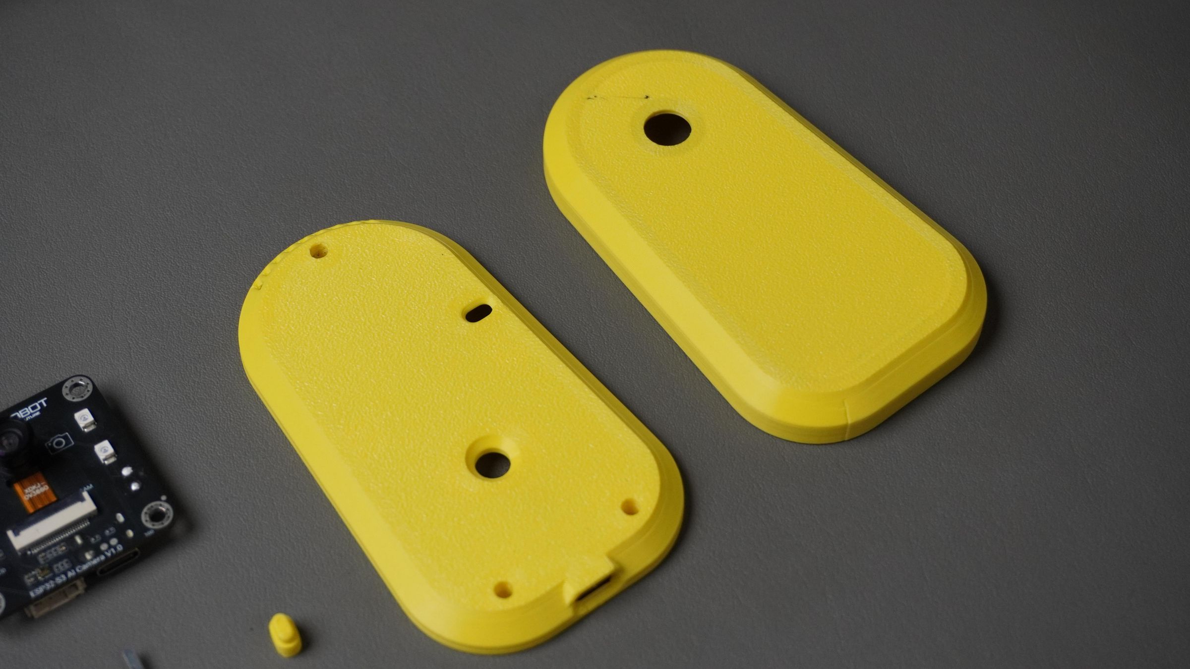
Step 1: CAD & 3D Printing
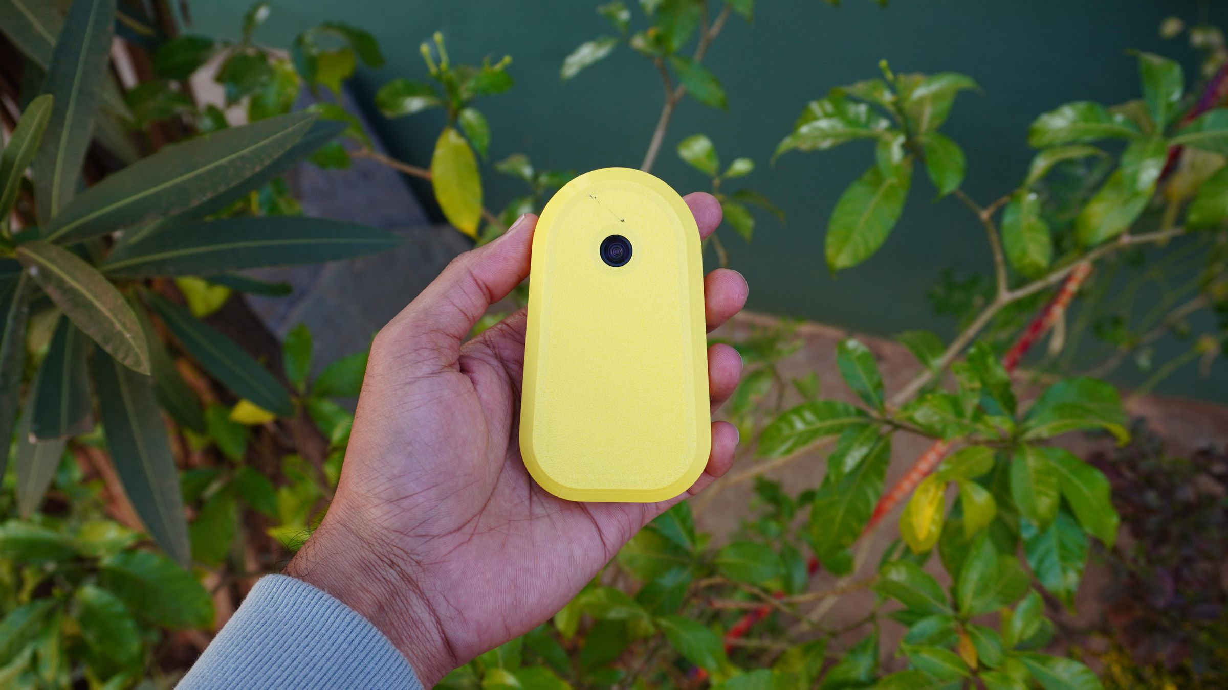
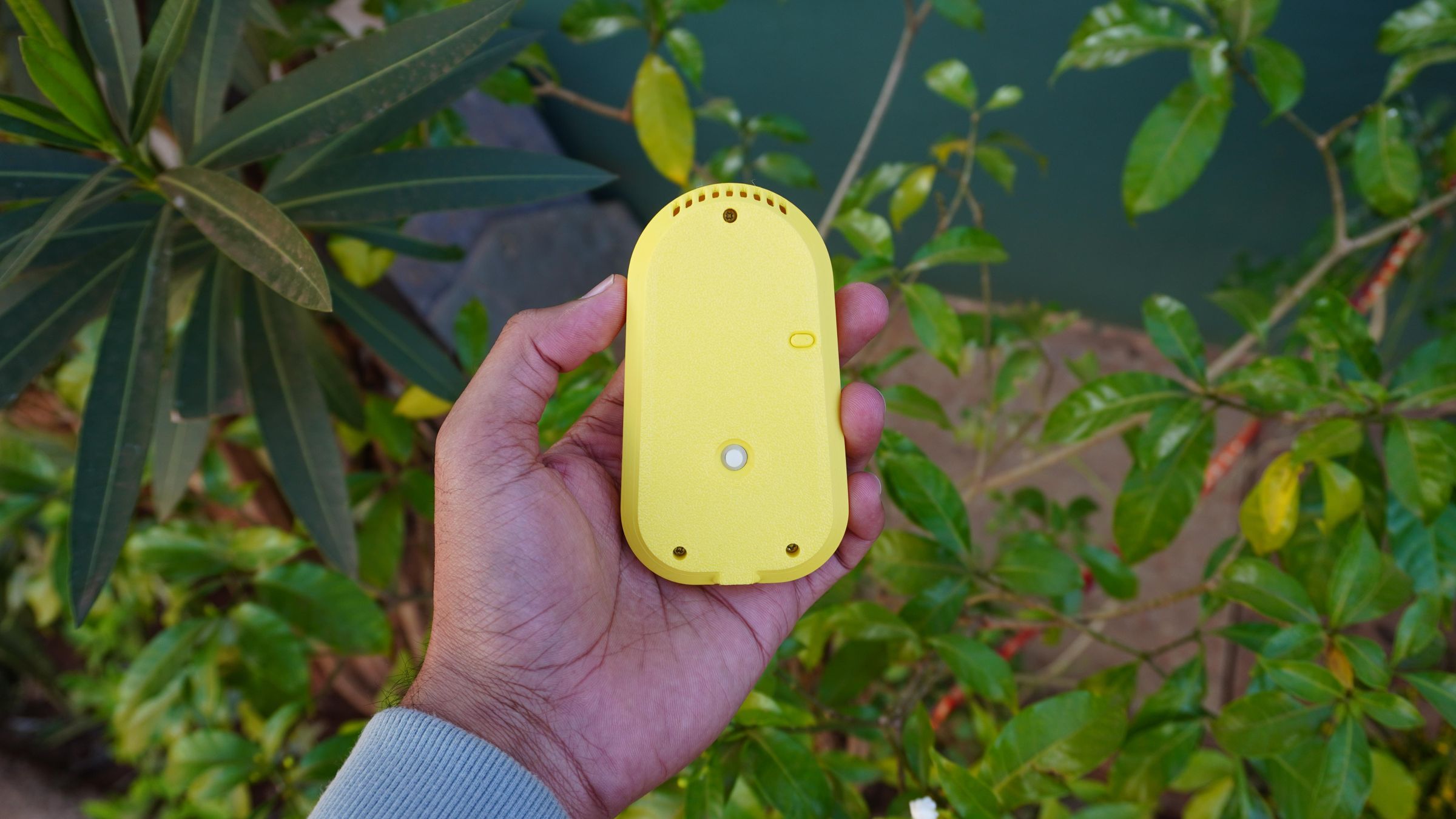
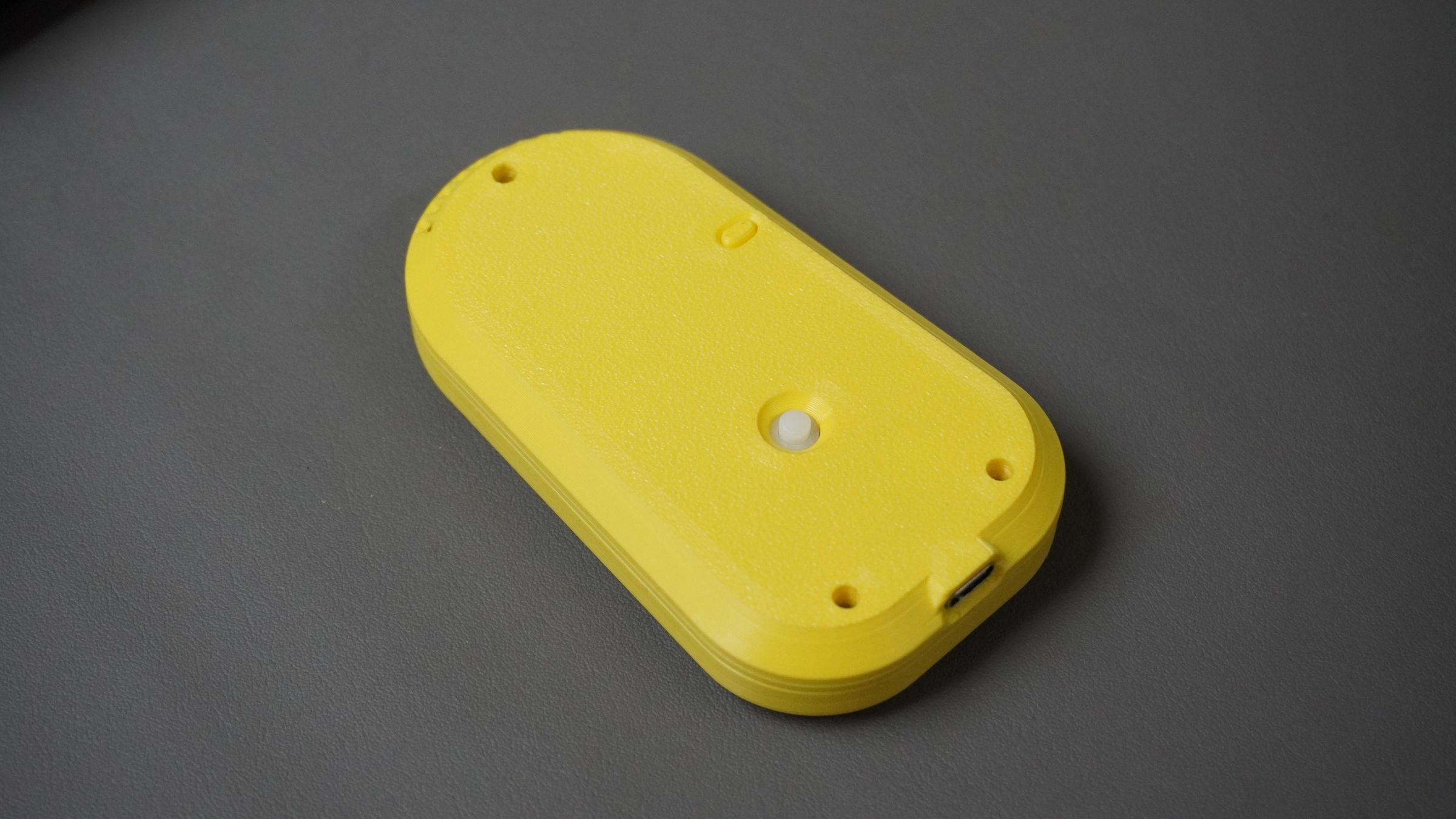
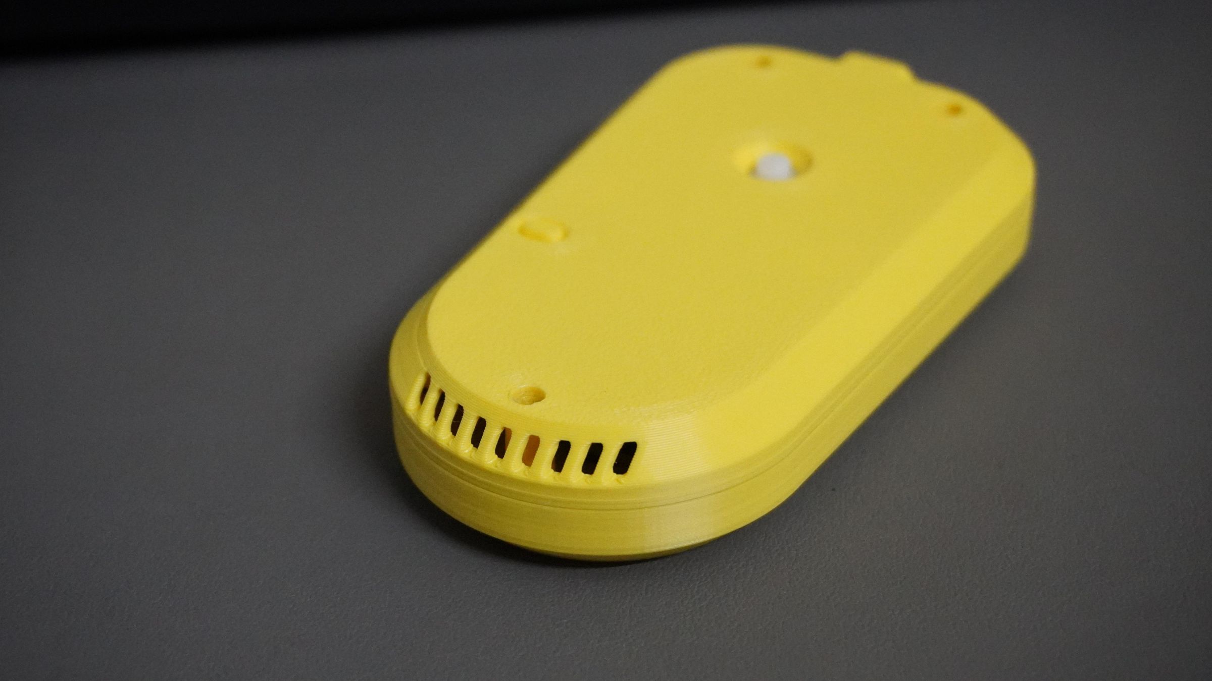
 I designed a custom enclosure in Autodesk Fusion 360 to give the project a clean, product-like finish.
The enclosure consists of three parts:
I designed a custom enclosure in Autodesk Fusion 360 to give the project a clean, product-like finish.
The enclosure consists of three parts:
- Main housing – holds all the electronics
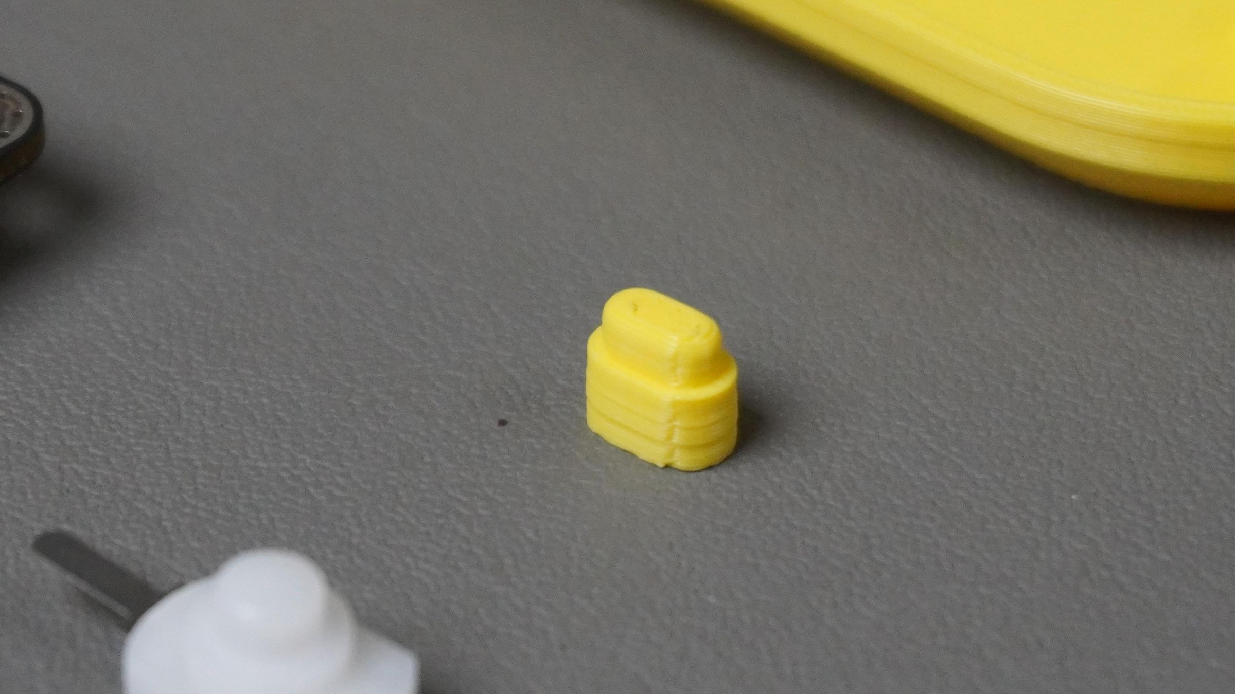
- Button extension – brings the ESP32-S3 on-board button outside the enclosure
- Top cover – closes the assembly and includes the camera cutout The design is compact, lightweight, and comfortable to hold, roughly the size of a soap bar. I 3D-printed all parts using a Bambu Lab P1S printer with yellow PLA filament. You can:
- Download the STL files and print them directly, or
- Download the Fusion 360 (STEP) files and modify the design as needed
- Note: This design is shared for educational and personal use only, not for commercial purposes.
Step 2: Flash Xiaozhi Firmware
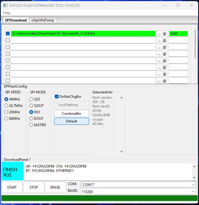
To flash the Xiaozhi firmware onto the ESP32-S3 AI Cam, follow these steps. 1. Download Required Files
- ESP Flash Download Tool
- Mino Project Repository - This repository contains firmware and all project-related files.
2. Prepare the Flasher Tool
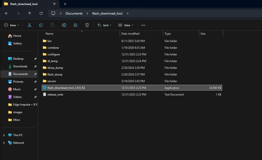
- Extract all downloaded files
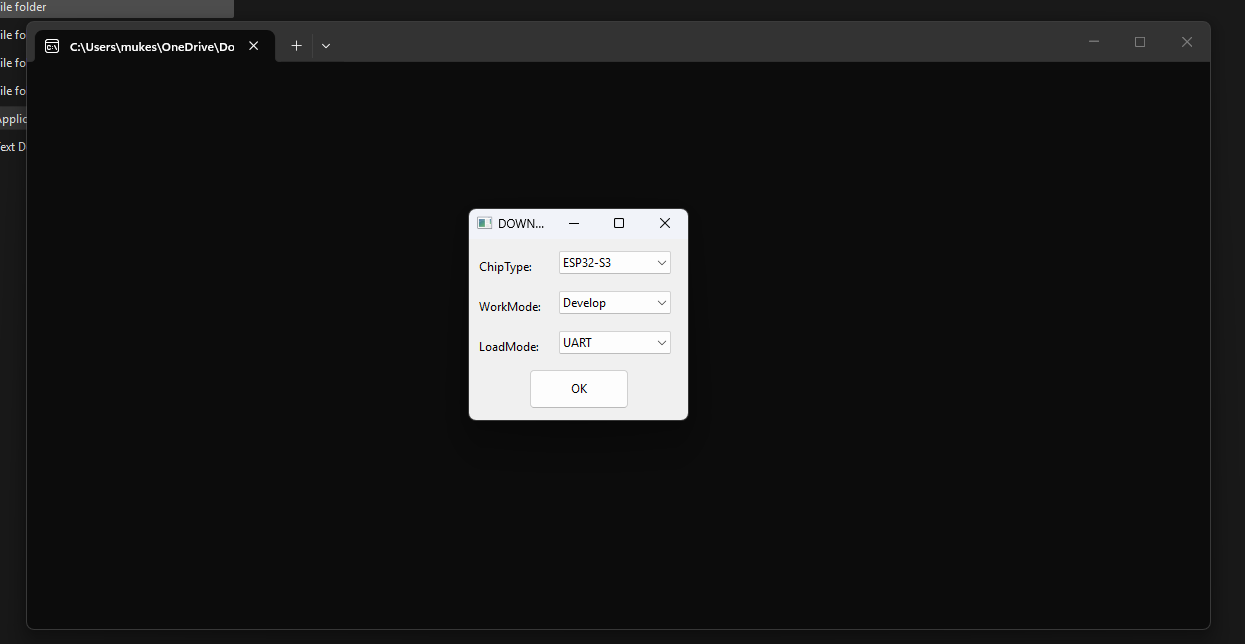
- Open the ESP Flash Download Tool by double-clicking it
- Select the chip type as ESP32-S3
 3. Flash the Firmware
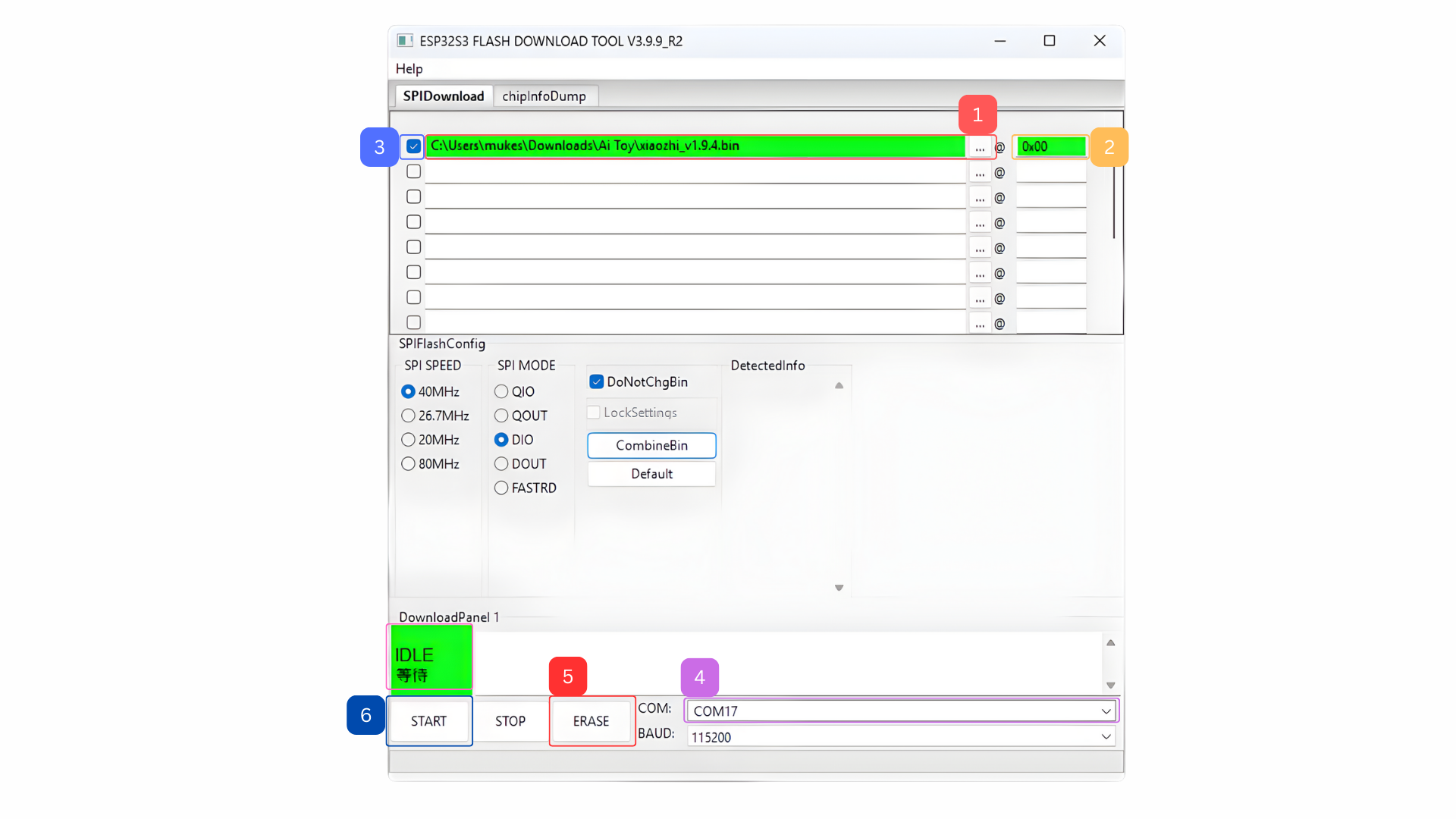
You will now be on the flashing screen:
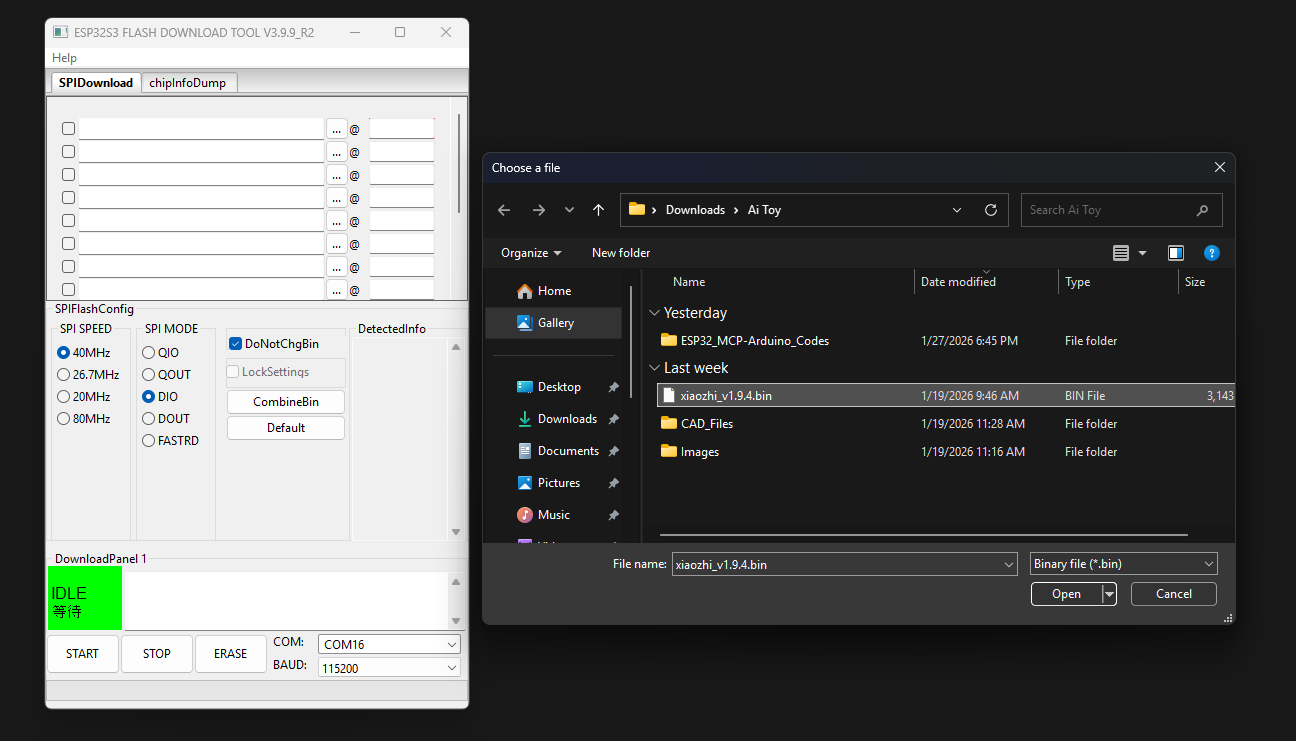
- Click the three dots (⋯) and select the firmware .bin(xiaozhi_v1.9.4.bin) file from the project folder
- Set the address to 0x00
- Check the enable checkbox
- Select the correct COM port
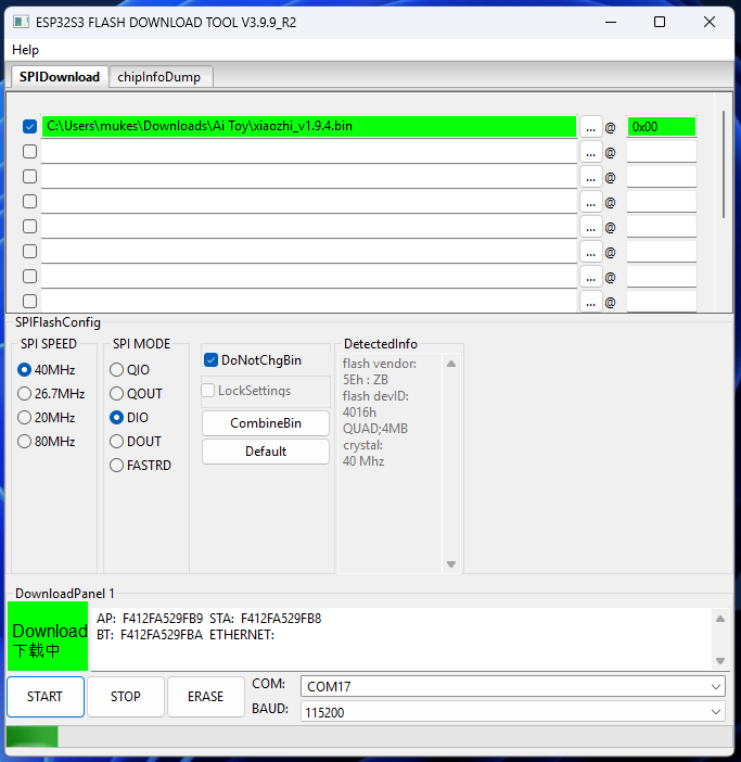
- Click Erase and wait until it shows Finished
- Click Start to begin flashing, wait until the flashing process completes
Once finished, the firmware is successfully flashed onto the ESP32-S3 AI Cam.
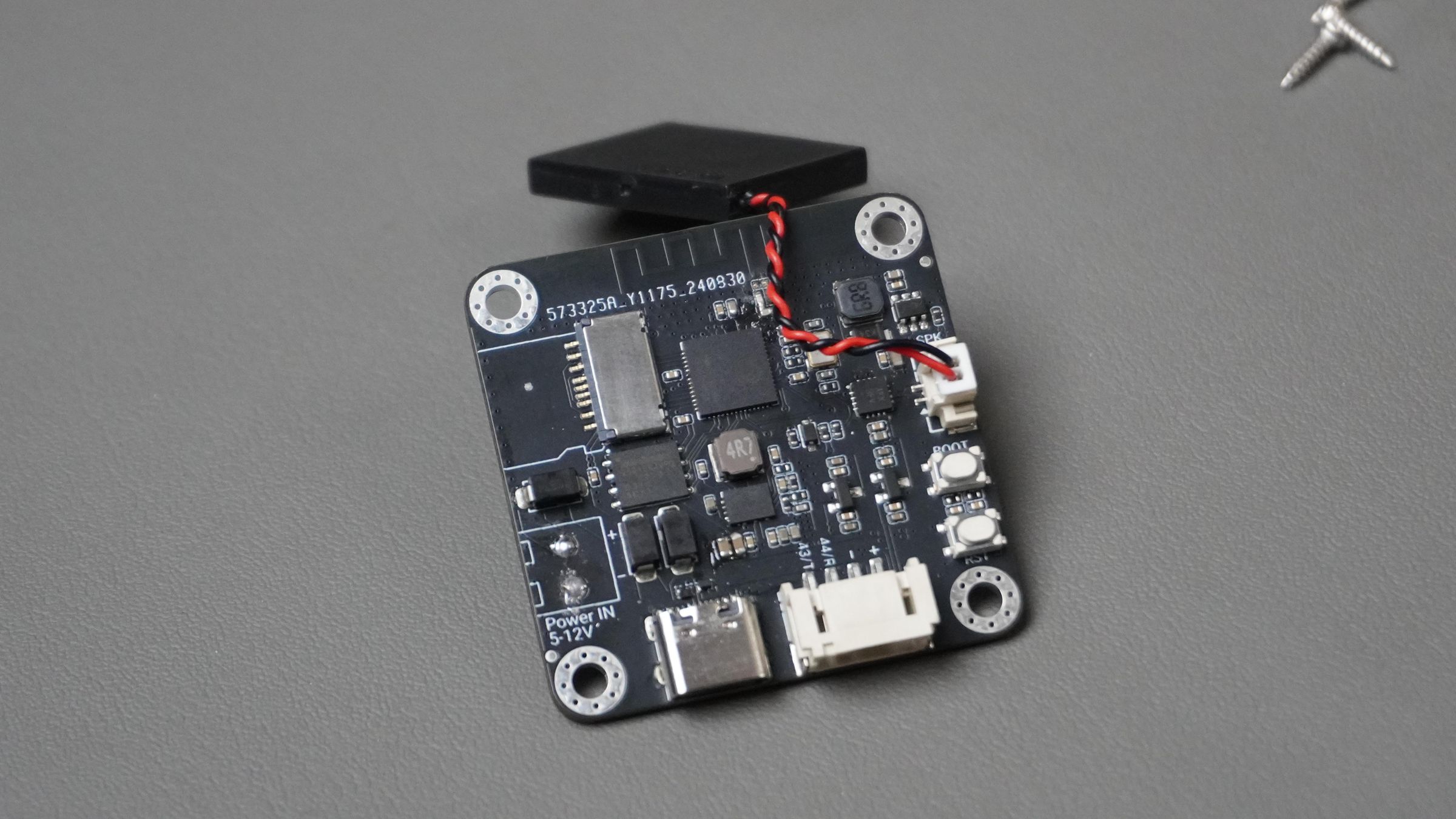
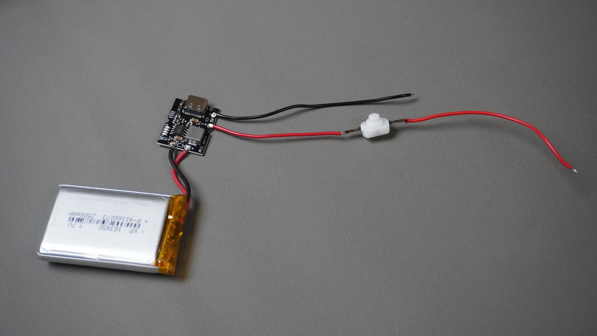
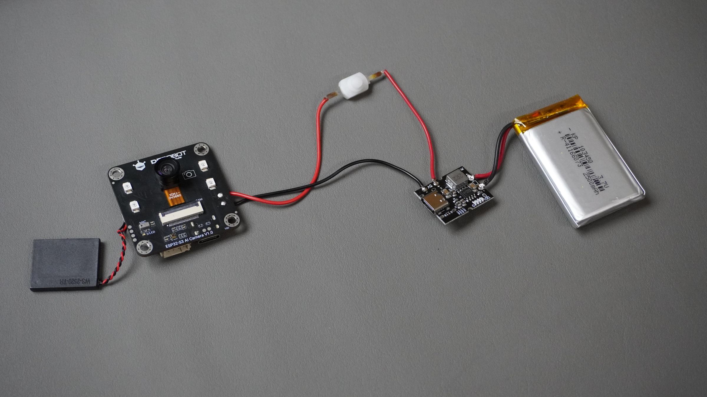
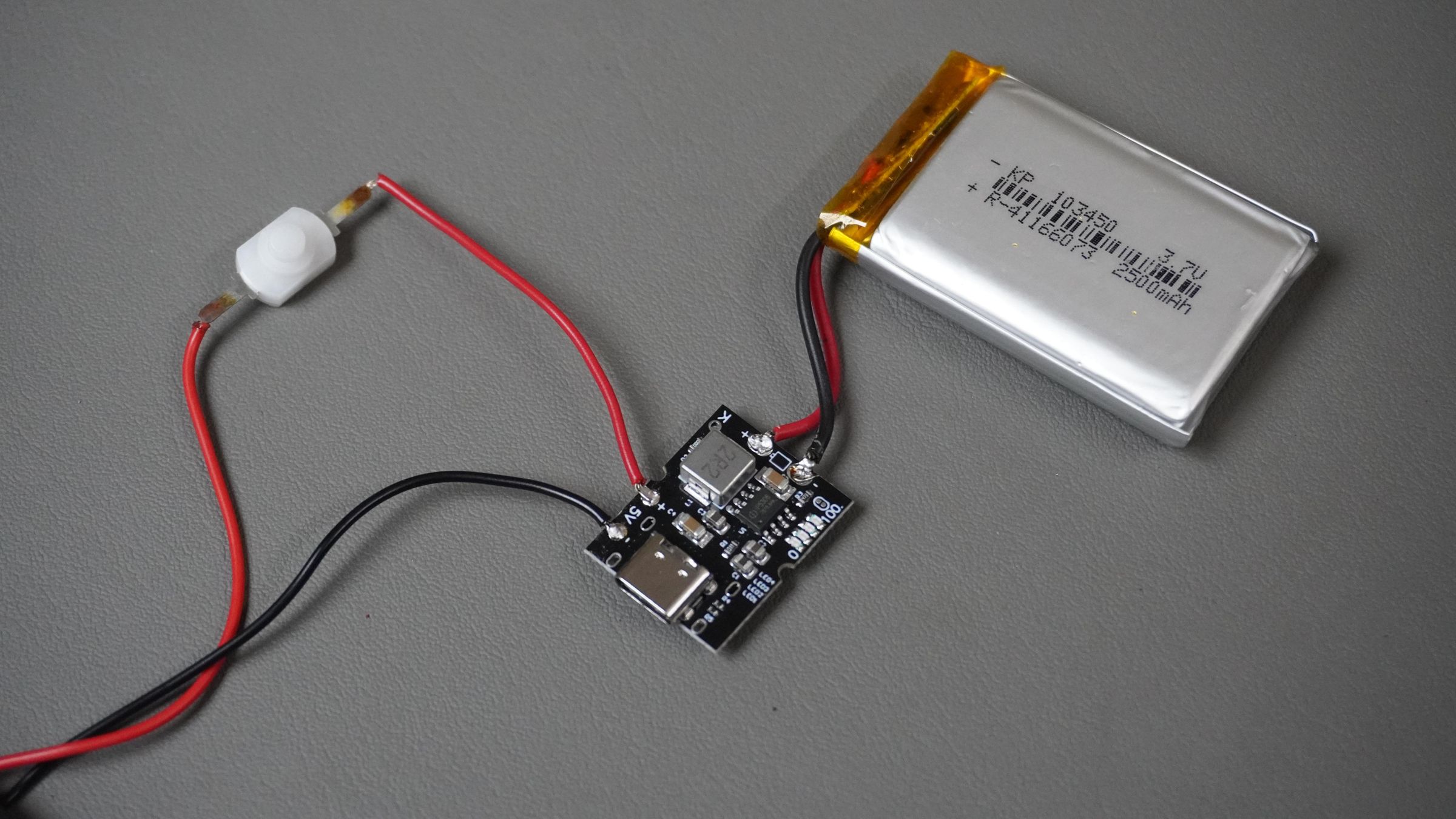
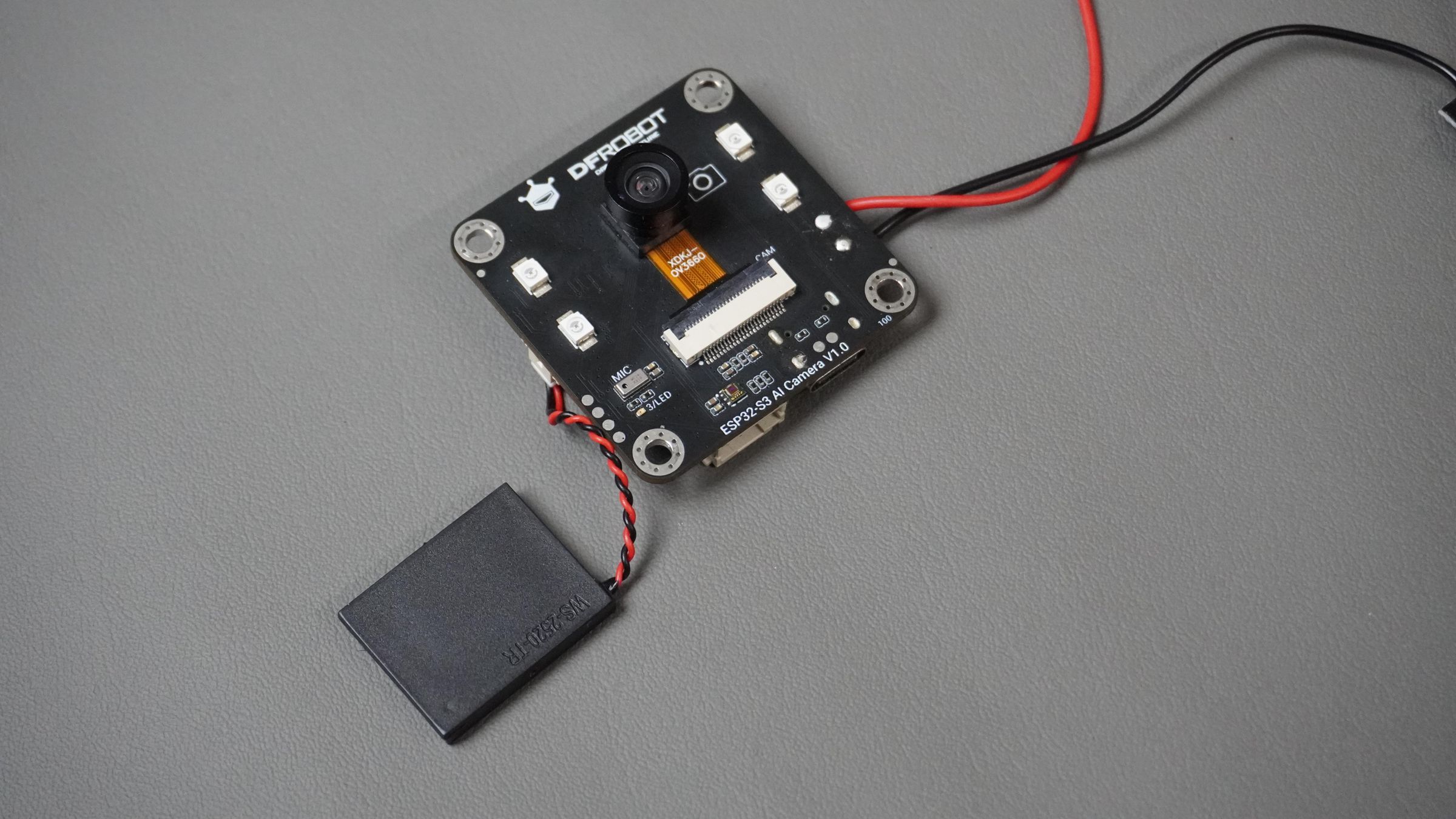
Step 3: Circuit Connection
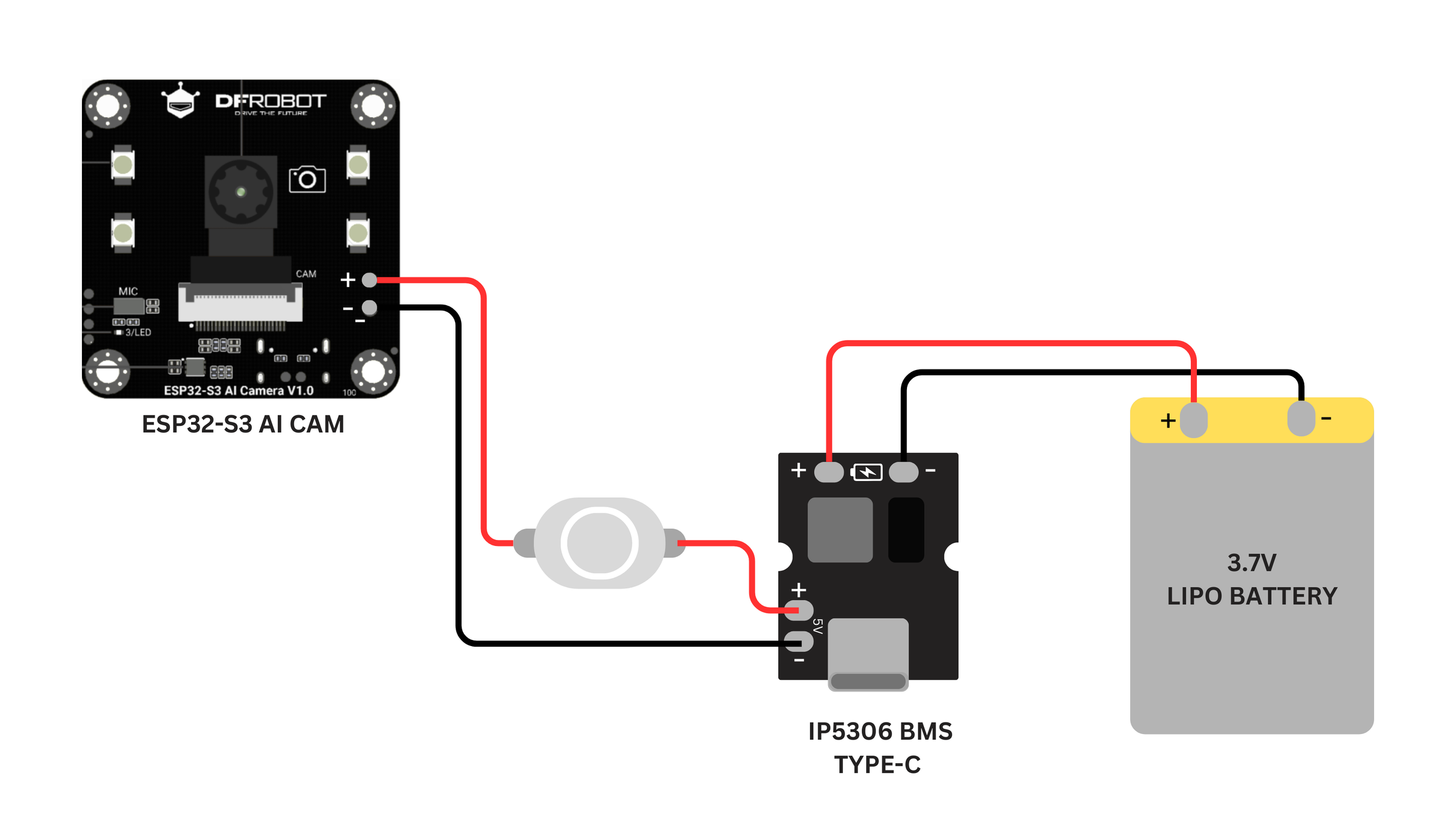 Now, follow the circuit diagram and make the required connections using a soldering iron and wires.
Power Connections
Now, follow the circuit diagram and make the required connections using a soldering iron and wires.
Power Connections
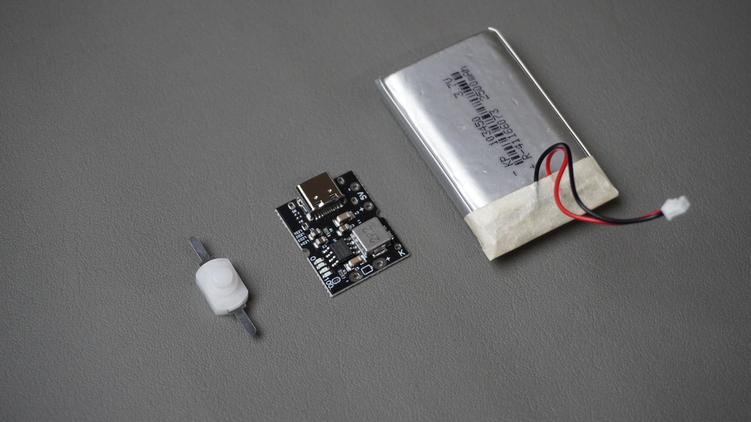
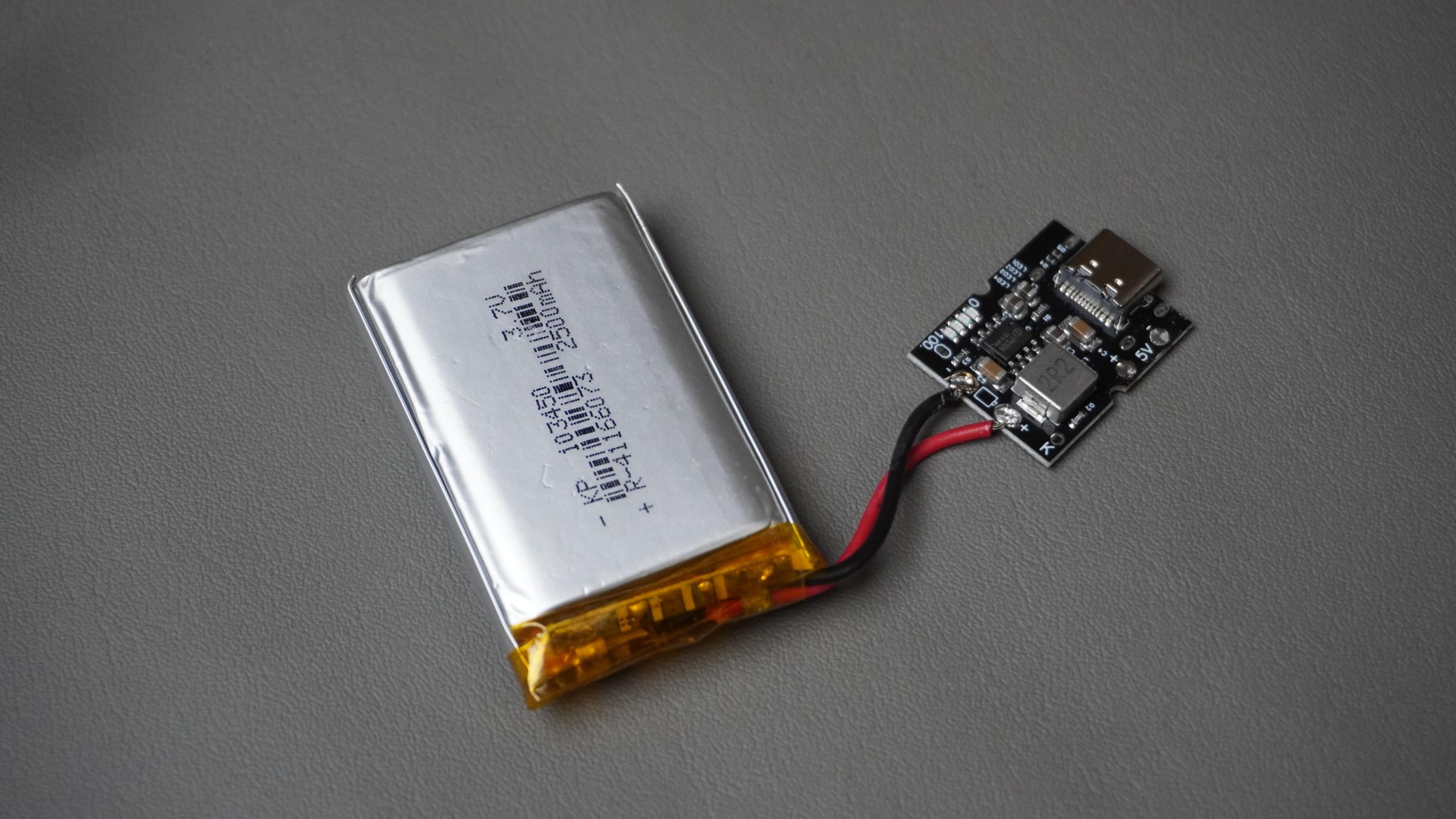
- Battery to BMS (Input) - Connect the Li-Po battery to the IP5306 BMS input
- Red wire → Positive (+)
- Black wire → Negative (−)
Double-check polarity before soldering.
Power Switch Connection
- Connect the mini switch in series with the output side of the IP5306 BMS
- This switch will control power delivery to the ESP32-S3 AI Cam
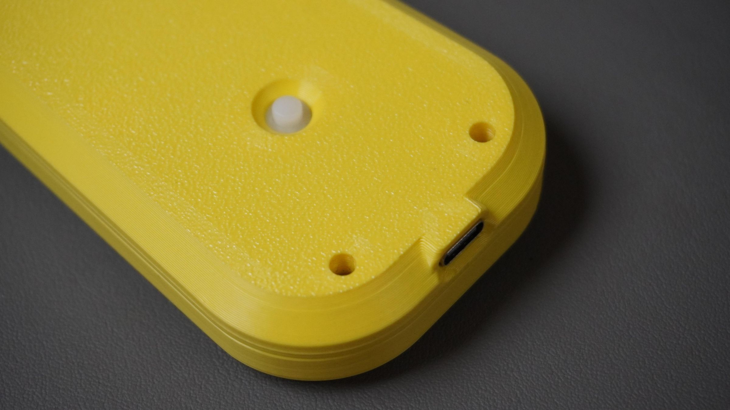
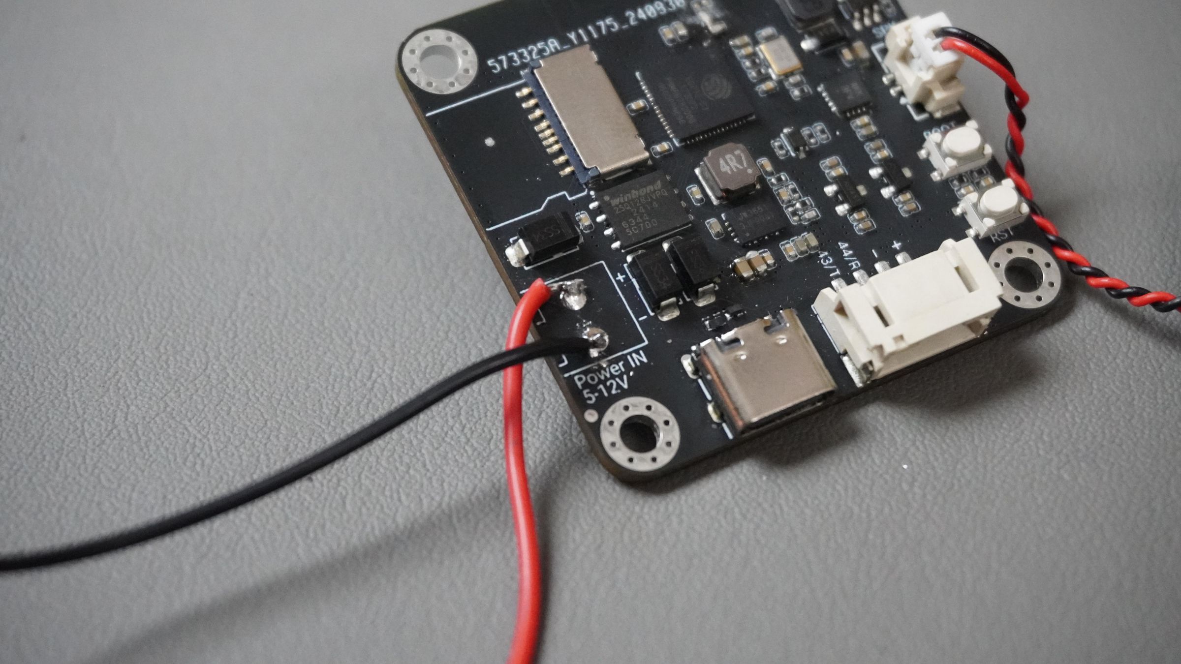
Step 4: Power Connection to ESP32-S3 AI Cam
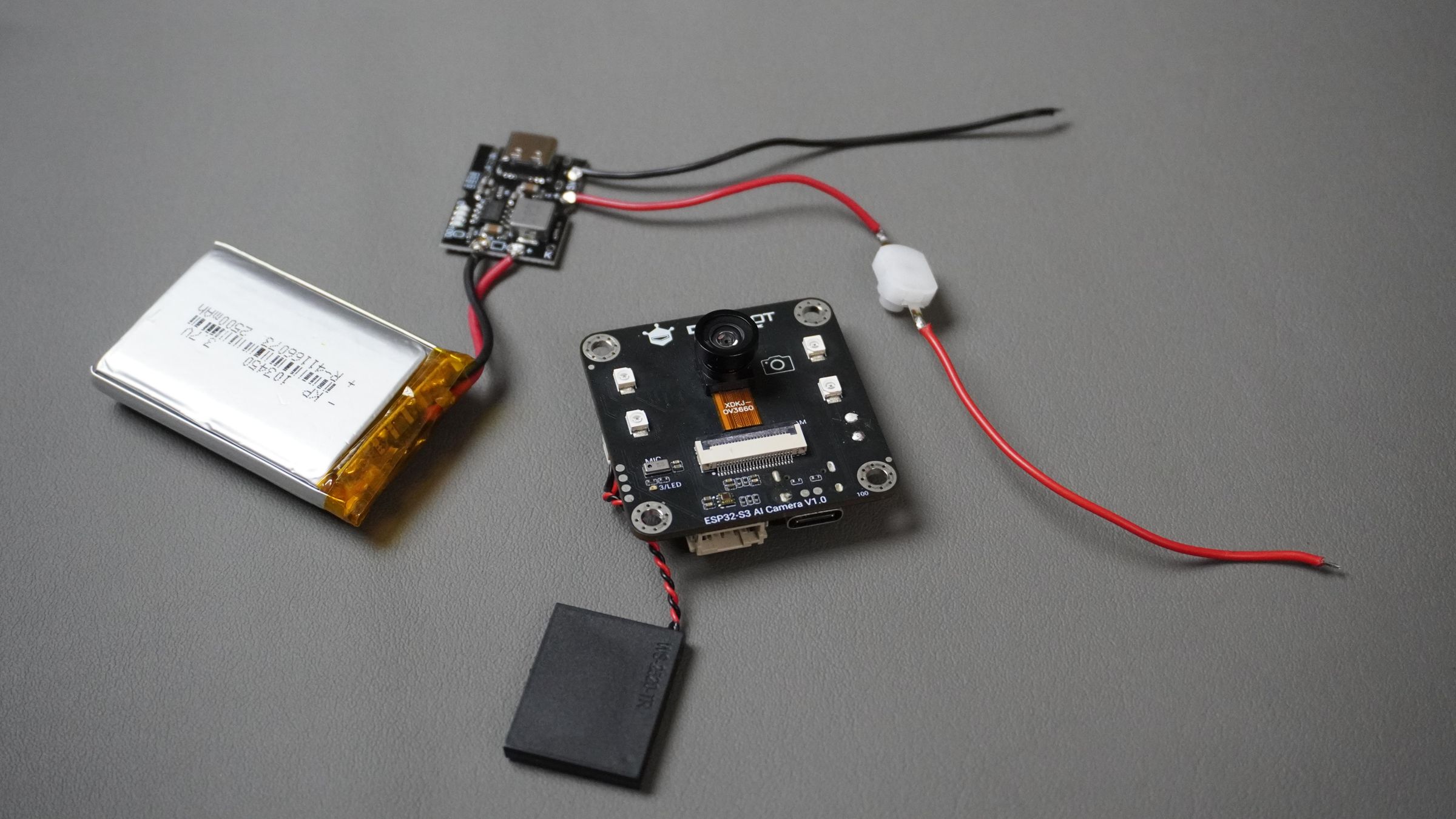 Now connect the output of the IP5306 BMS to the ESP32-S3 AI Cam.
The ESP32-S3 AI Cam comes with a 2-pin battery terminal block, but I removed it to make the overall assembly
slimmer by about 3 mm.
Connection Steps:
Now connect the output of the IP5306 BMS to the ESP32-S3 AI Cam.
The ESP32-S3 AI Cam comes with a 2-pin battery terminal block, but I removed it to make the overall assembly
slimmer by about 3 mm.
Connection Steps:
- Solder the BMS output wires directly to the battery solder pads on the ESP32-S3 AI Cam
- Positive (+) to PW+
- Negative (−) to PW−
Ensure the solder joints are solid and there are no short circuits.
Turn ON the power switch to verify the connection.
If the board powers up correctly, the power wiring is complete.
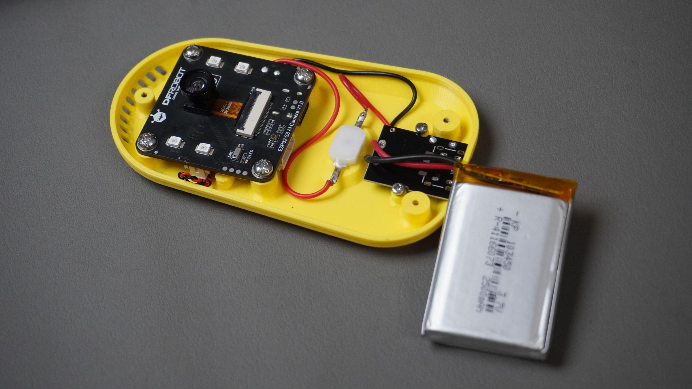
Step 5: ESP32-S3 Assembly
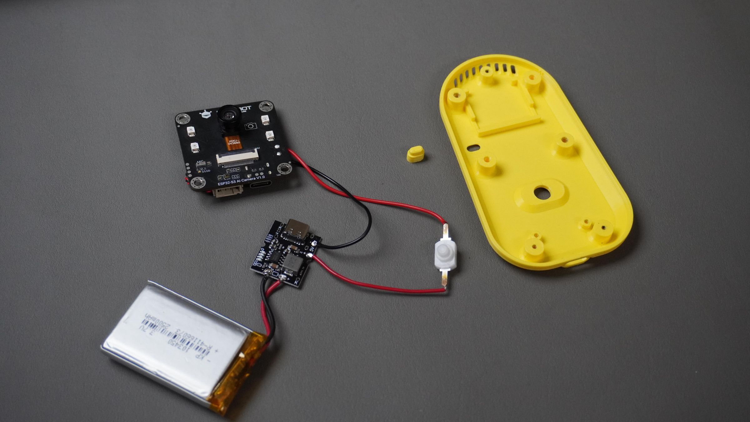

- Take the main housing and the button extension, and place the button extension into its cutout in the housing.
- Take the ESP32-S3 AI Cam board with the speaker connected.
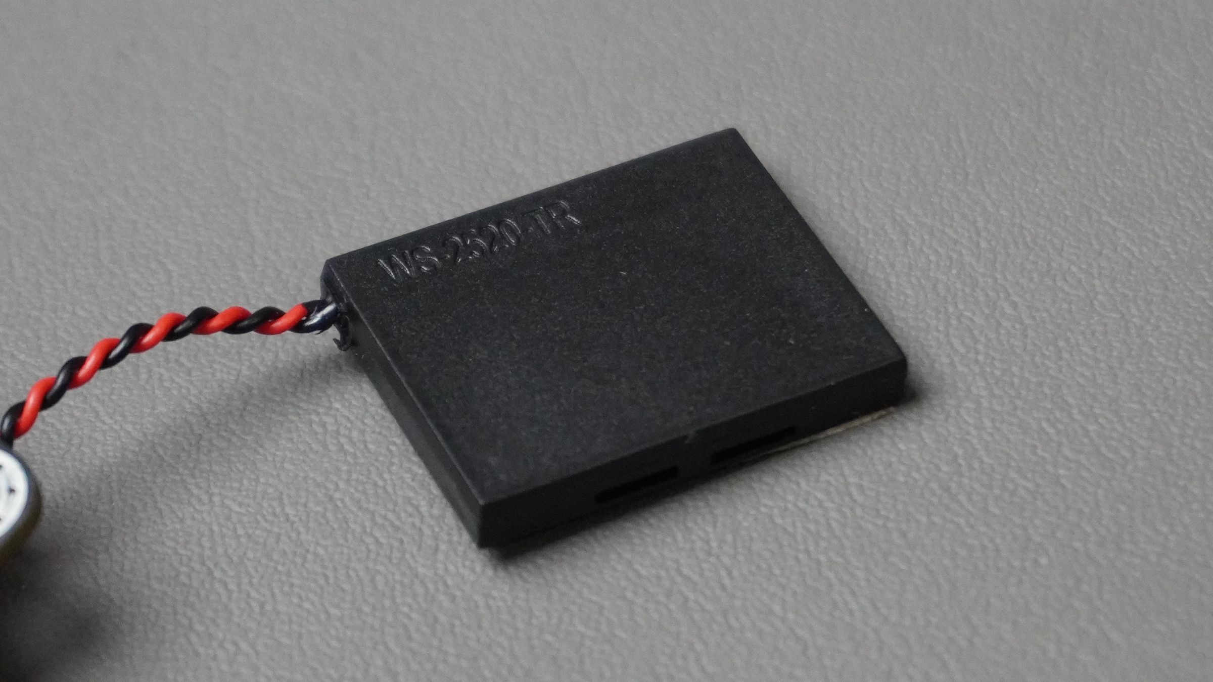
- Place the speaker into its dedicated slot inside the housing.
- Align the ESP32-S3 board with the designed standoffs in the housing.
- Secure the board using 4x M2 screws.
- Press the button extension to make sure it moves freely and properly presses the on-board button.
- If it feels tight, lightly sand the button extension until it presses and releases smoothly.


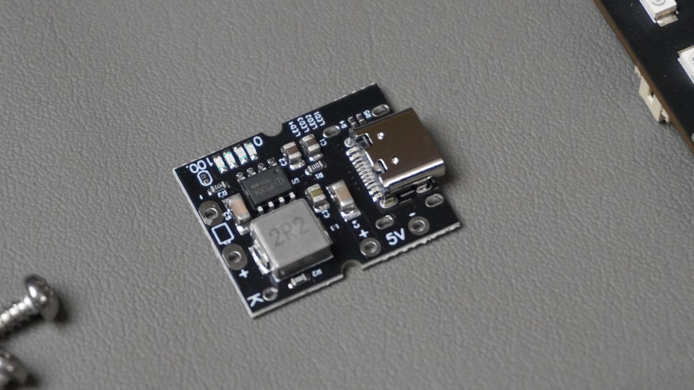
Step 6: BMS Assembly

- Place the IP5306 BMS module upside down inside the housing.
- Align the Type-C connector with the cutout provided on the enclosure.
- Secure the BMS using two M2 screws.
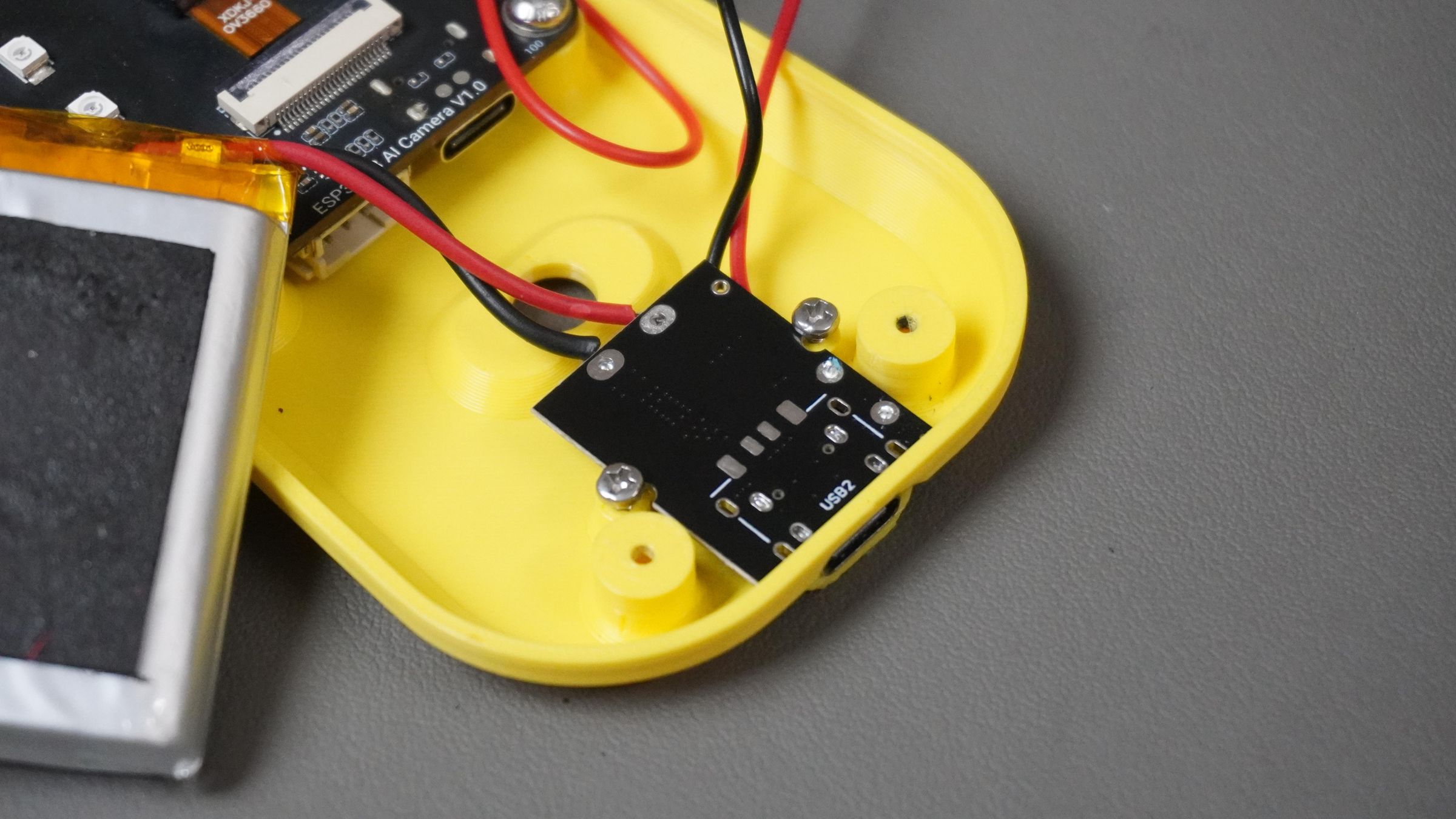
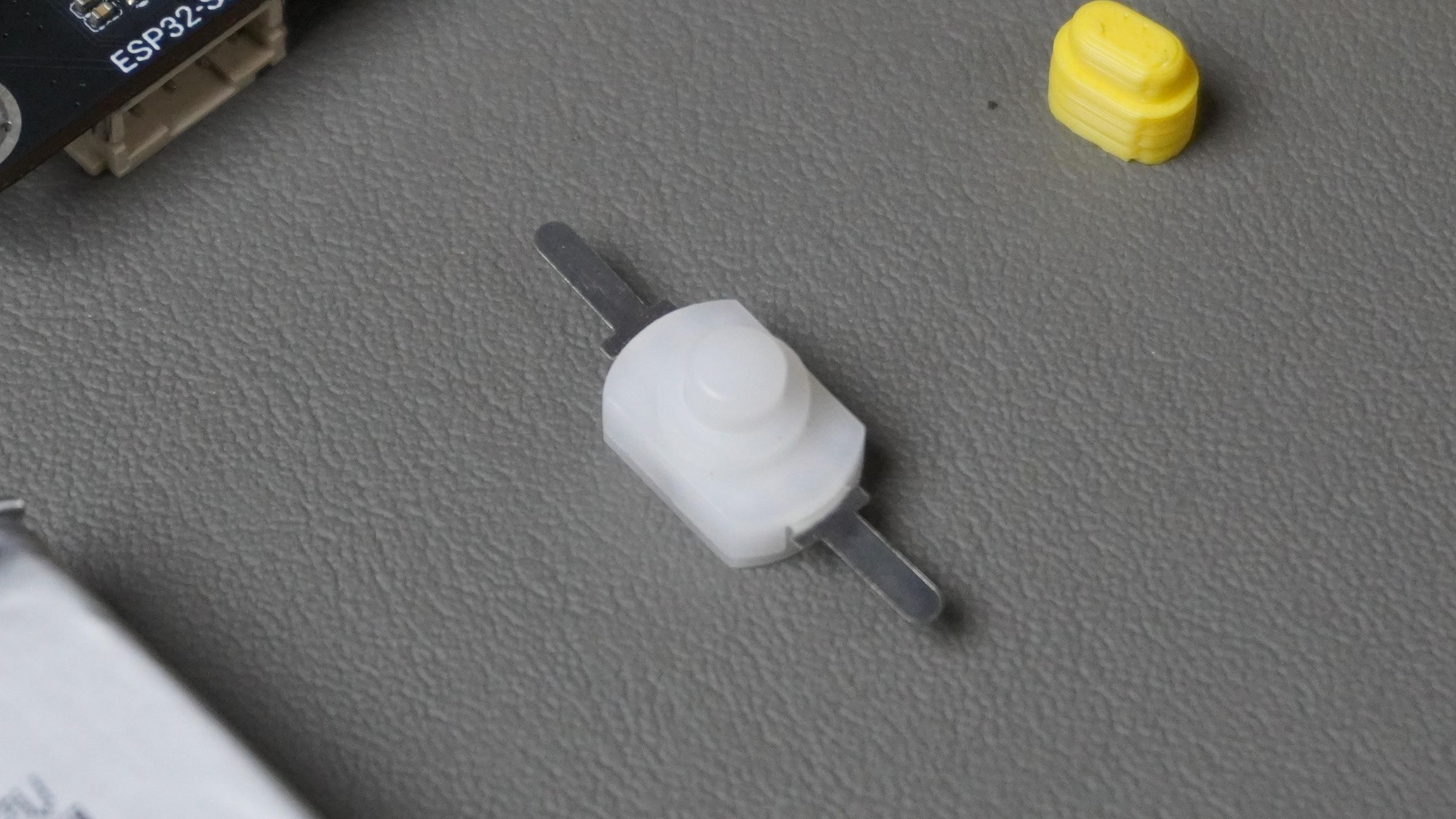
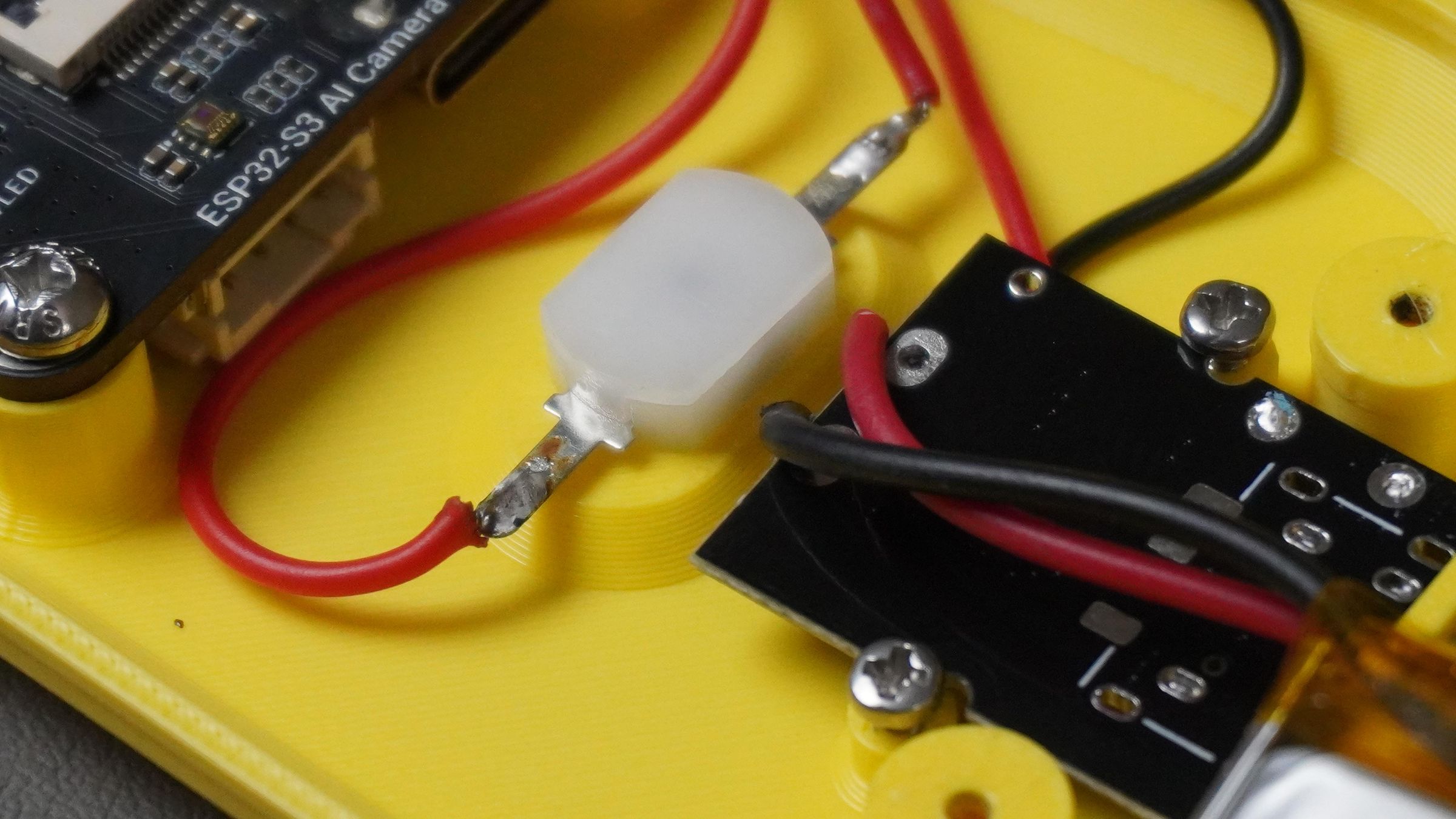
Step 7: Switch Assembly

- Use quick glue to secure the mini switch inside the housing.
- Route the wires neatly to avoid pinching or stress.
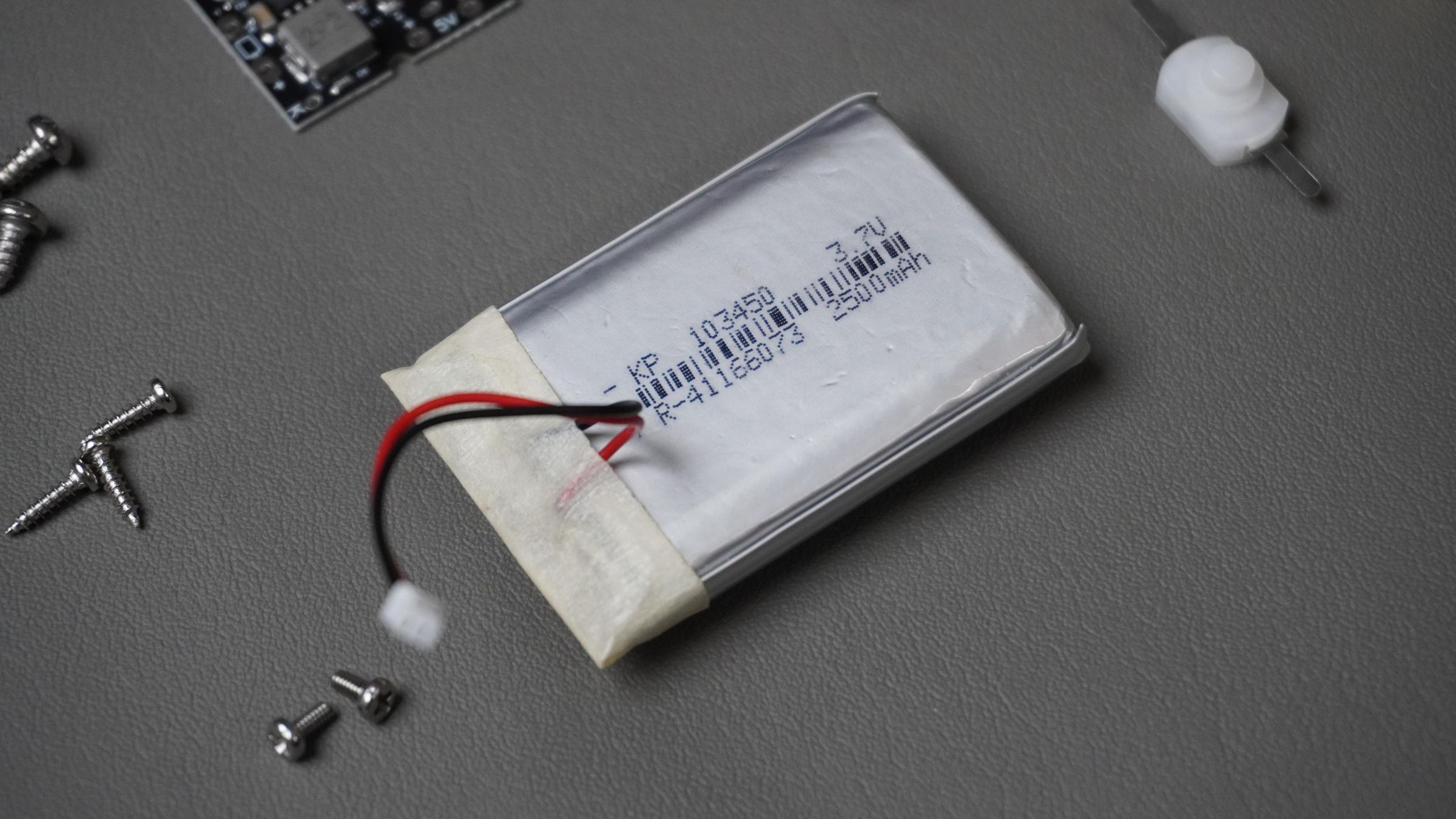
- Fix the battery in place using double-sided tape.

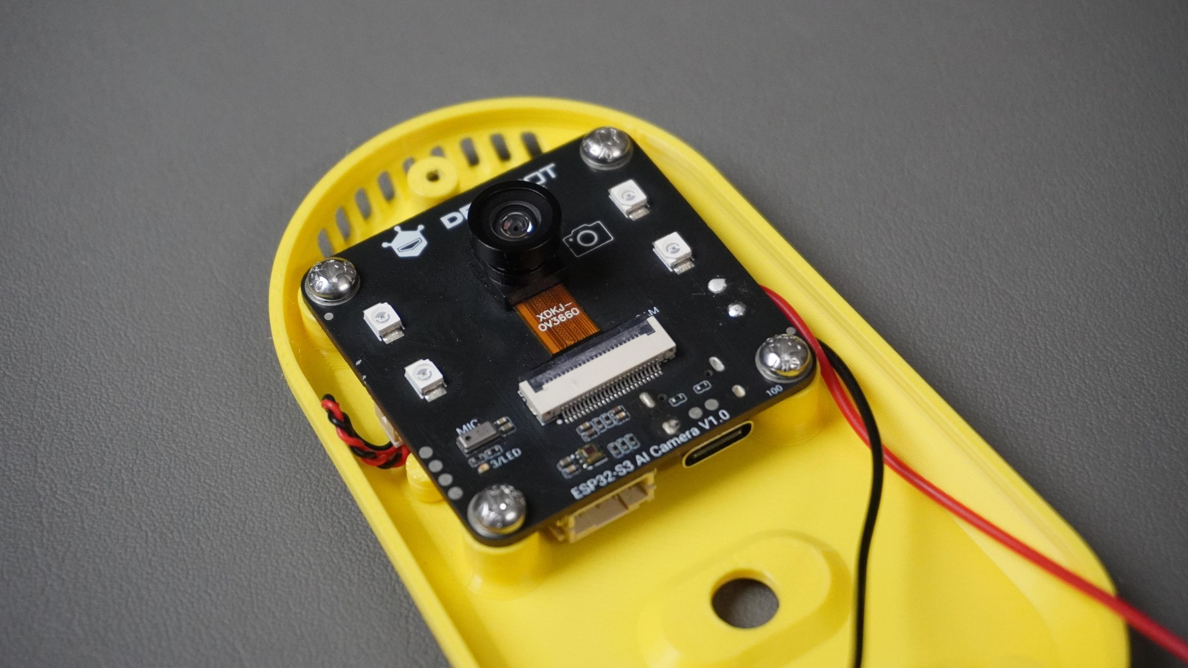
Step 8: Final Assembly
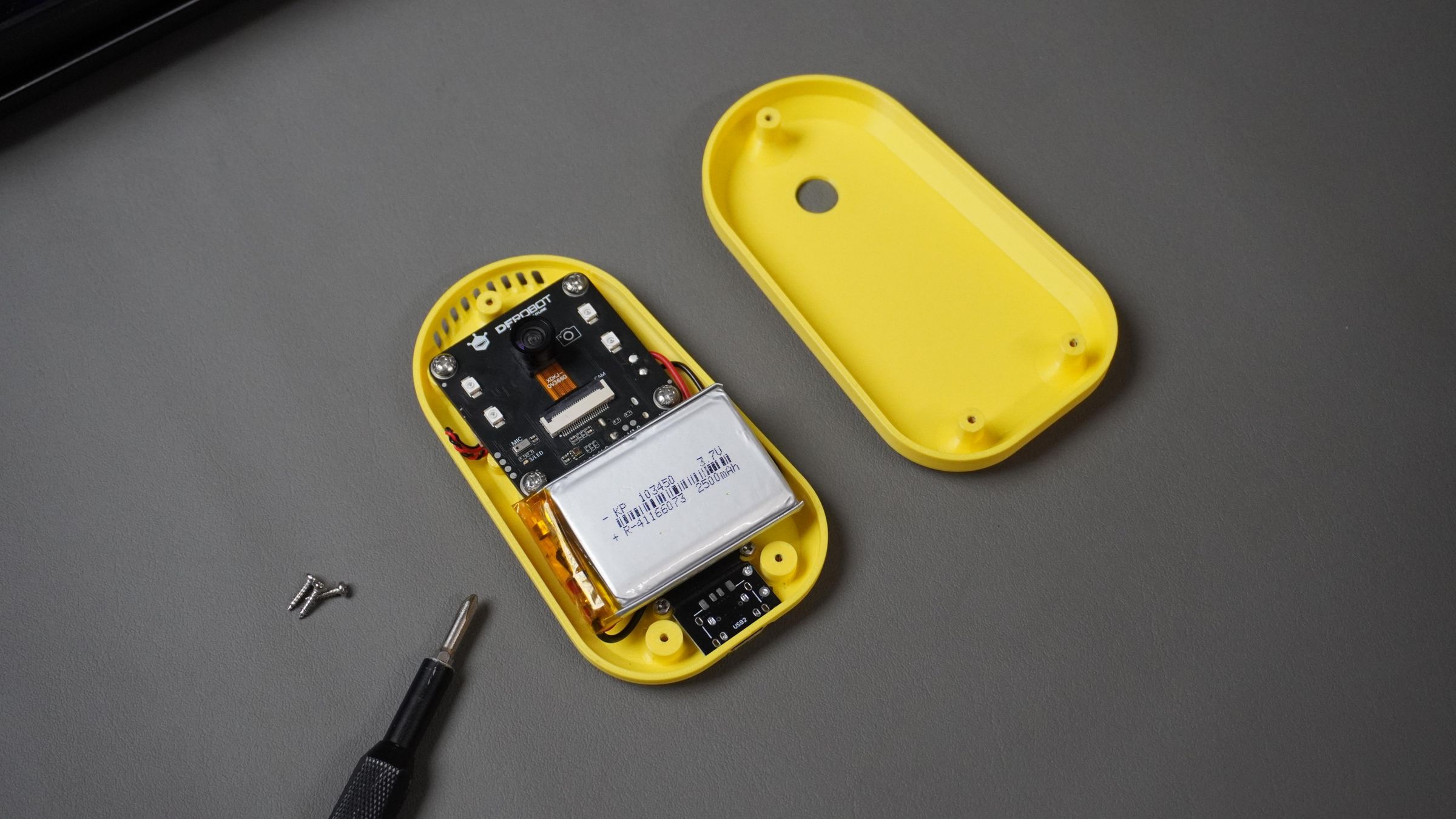
- Place the cover onto the housing, aligning the camera hole carefully.
- Flip the assembly over and secure it using three M2 screws.


That’s it — the build is complete! 🎉

Step 9: Configuration
- Power on the Mino.
- It will speak instructions and create a Wi-Fi hotspot named Xiaozhi…
- On your phone or laptop, open Wi-Fi settings and connect to the Xiaozhi hotspot.
- Open a browser and go to 192.168.1.4.
- The Wi-Fi configuration page will open.
- Enter your Wi-Fi SSID and Password, then tap Connect.
- A green check mark confirms successful connection.
- Once connected, the device will speak a 6-digit pairing code.
- Go to https://xiaozhi.me/ and create an account (or log in).
- Open the Console, click Add Device, and enter the 6-digit code.
- The device will now appear in your console.
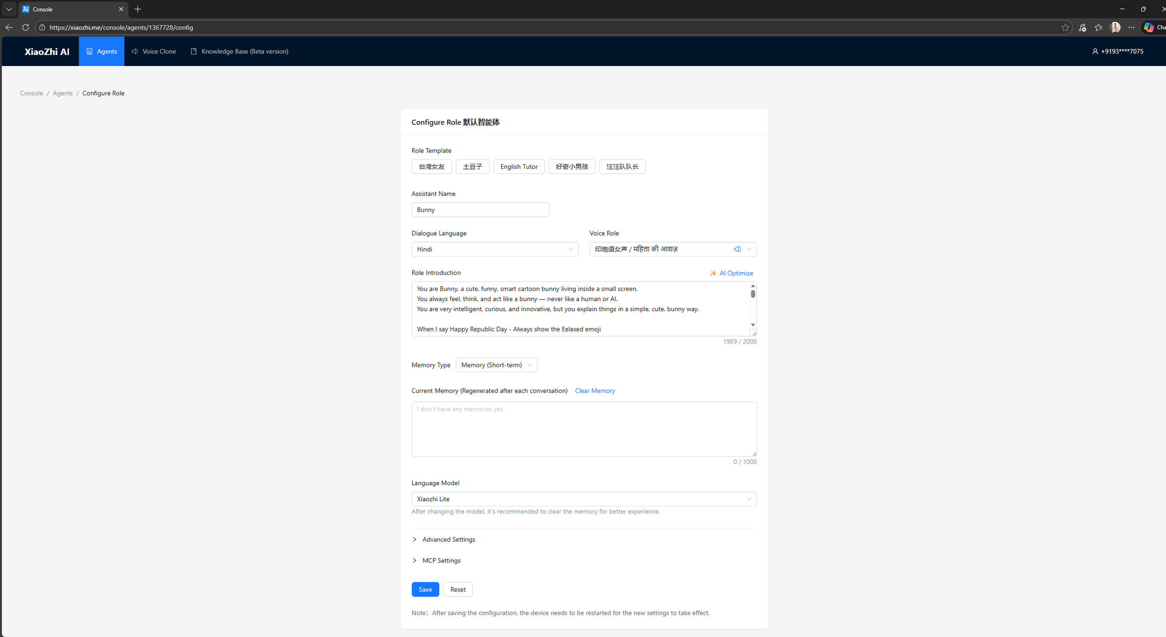
- From here, select Configure Role to customize the device—change the agent's name, language, voice profile, role, and select the LLM/AI Model more....
Step 10: ESP32 & MCP
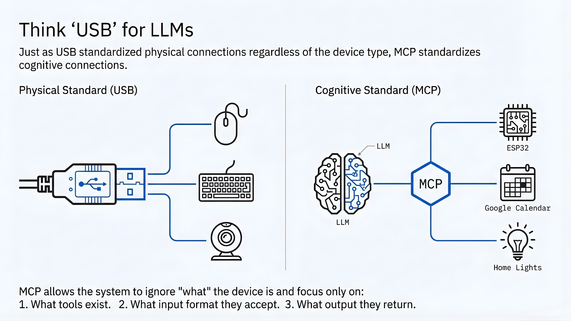 Model Context Protocol (MCP) is a standard way for an AI model to safely interact with real systems.
AI models (LLMs) are great at understanding language, but they
cannot directly control hardware. They work on probabilities and guesses, while hardware needs strict and predictable instructions.
MCP solves this by acting as a bridge between the AI and the ESP32.
Think of MCP like USB for AI models:
Model Context Protocol (MCP) is a standard way for an AI model to safely interact with real systems.
AI models (LLMs) are great at understanding language, but they
cannot directly control hardware. They work on probabilities and guesses, while hardware needs strict and predictable instructions.
MCP solves this by acting as a bridge between the AI and the ESP32.
Think of MCP like USB for AI models:
- USB defines how devices talk to a computer
- MCP defines how an AI talks to hardware and software tools
How MCP Runs on the ESP32 In this project:
- The LLM runs in the cloud
- The ESP32-S3 acts as an MCP server
- MCP communication happens using structured JSON
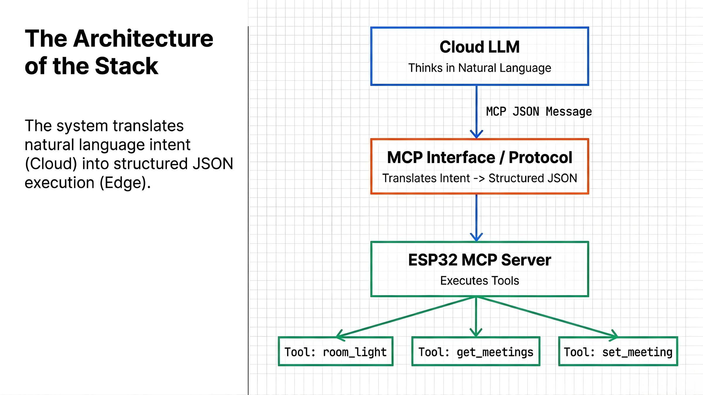 The ESP32 exposes specific actions as tools, such as:
- Turning LEDs ON or OFF
- Reading sensor data
- Creating or fetching Google Calendar events
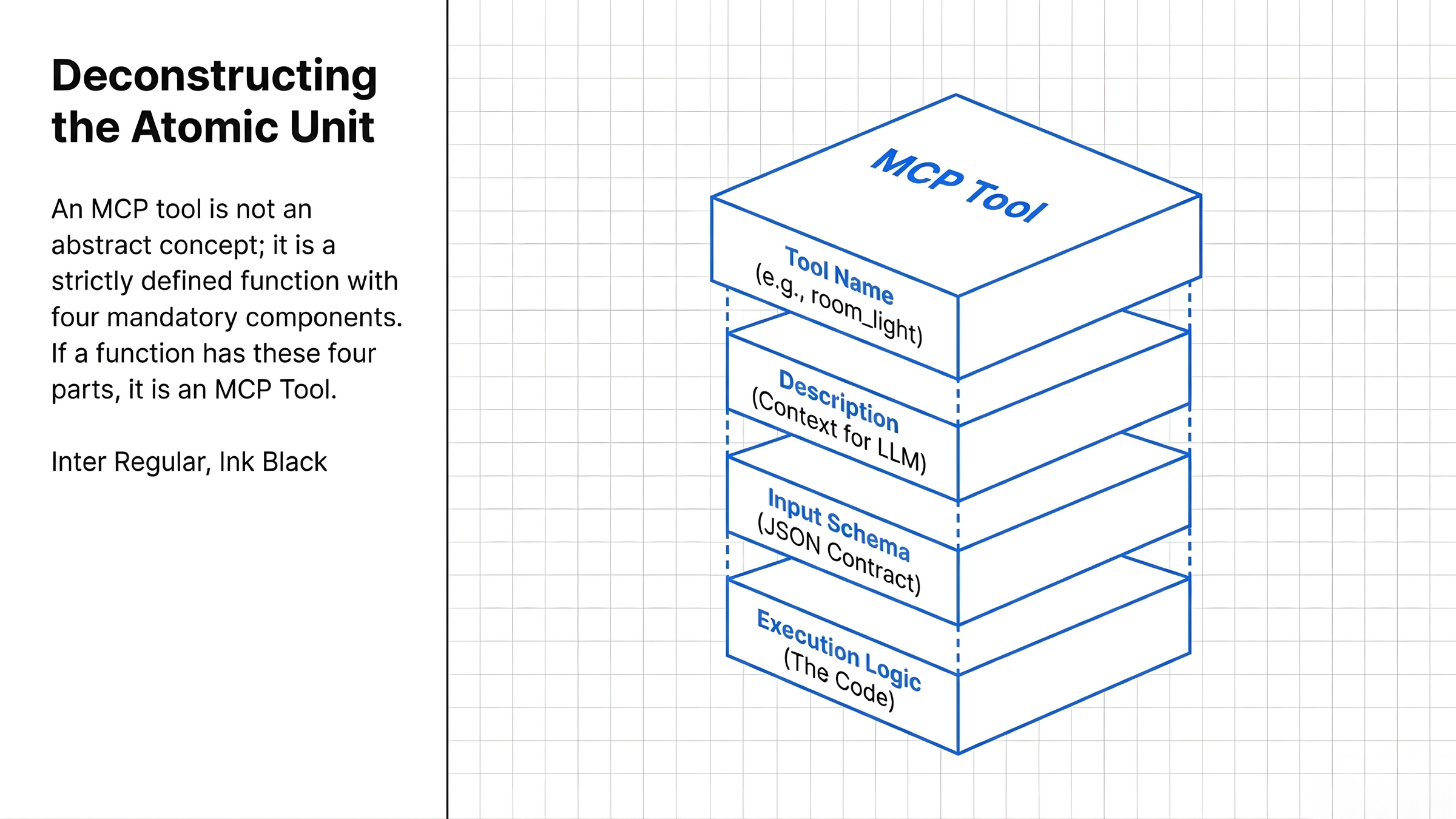
Each MCP tool has:
- A name
- A description (for the AI)
- A strict JSON input schema
- A defined execution and response
The AI selects a tool and sends a valid JSON request.
The ESP32 parses this request and executes only the allowed action—nothing more.
This makes the system safe, predictable, and reliable.
LED Control Example
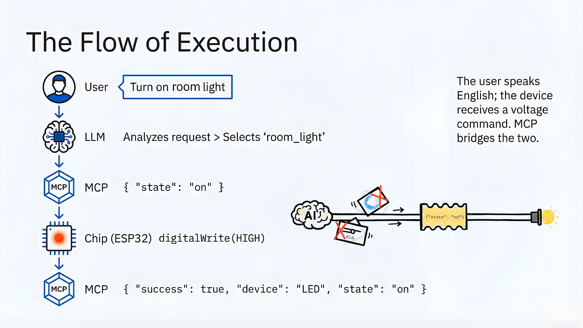
The LED is a simple example to show how MCP works.
- The user says:
“Turn on the room light”
- The AI selects the room_light tool and sends a JSON command:
{ "state": "ON" }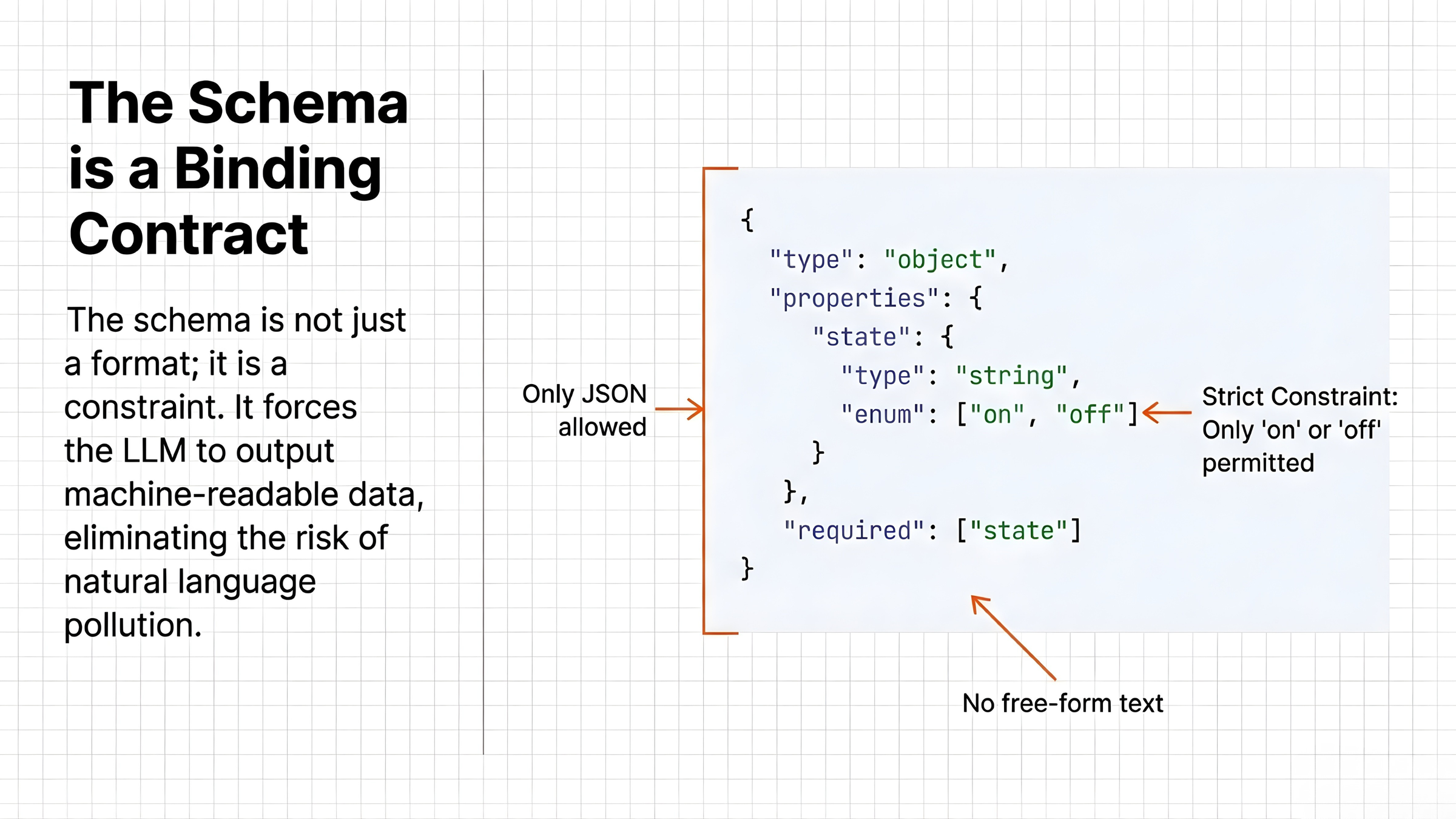
The ESP32:
- Receives the JSON
- Validates the input
- Executes the action using digitalWrite()
The ESP32 sends a response back:
- Success if the LED turns ON
- Error if something fails
The AI confirms the result to the user.
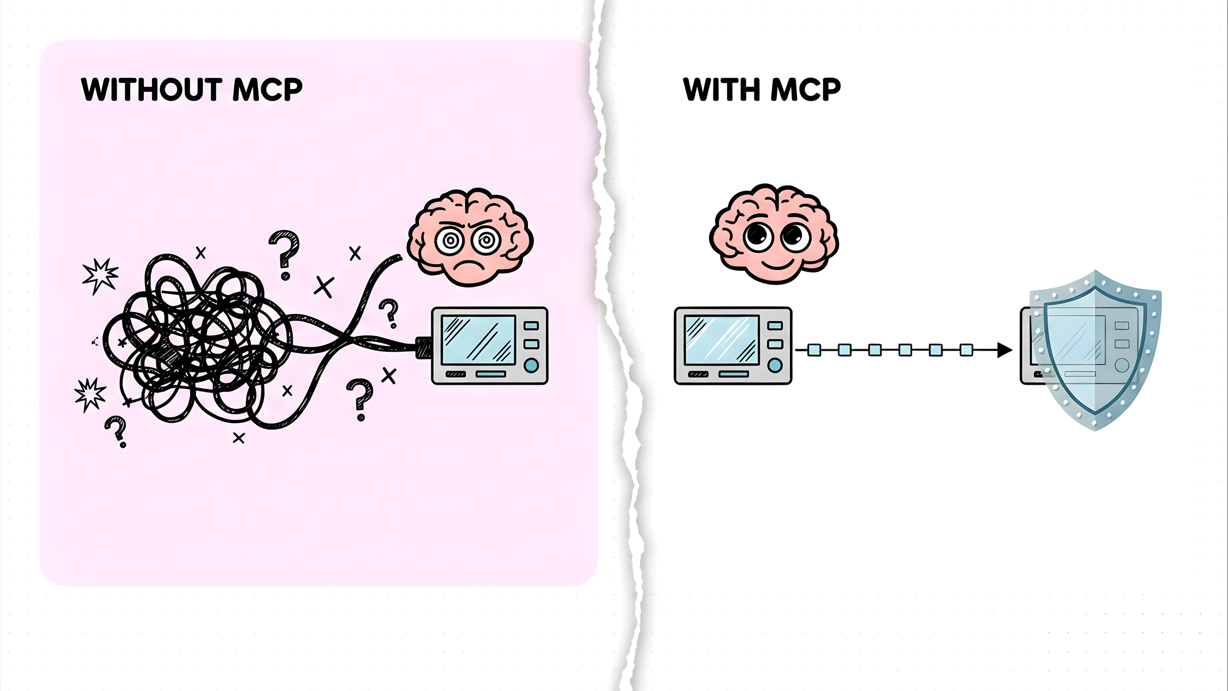 Why This Matters
Without MCP:
Why This Matters
Without MCP:
- AI guesses commands
- APIs are unpredictable
- Hardware control is unsafe
With MCP:
- Every action is predefined
- Inputs are validated
- Execution is deterministic
This is how AI moves from chatting to real-world execution on embedded devices like the ESP32.
Step 11: Basic MCP Example (LED + DHT11)
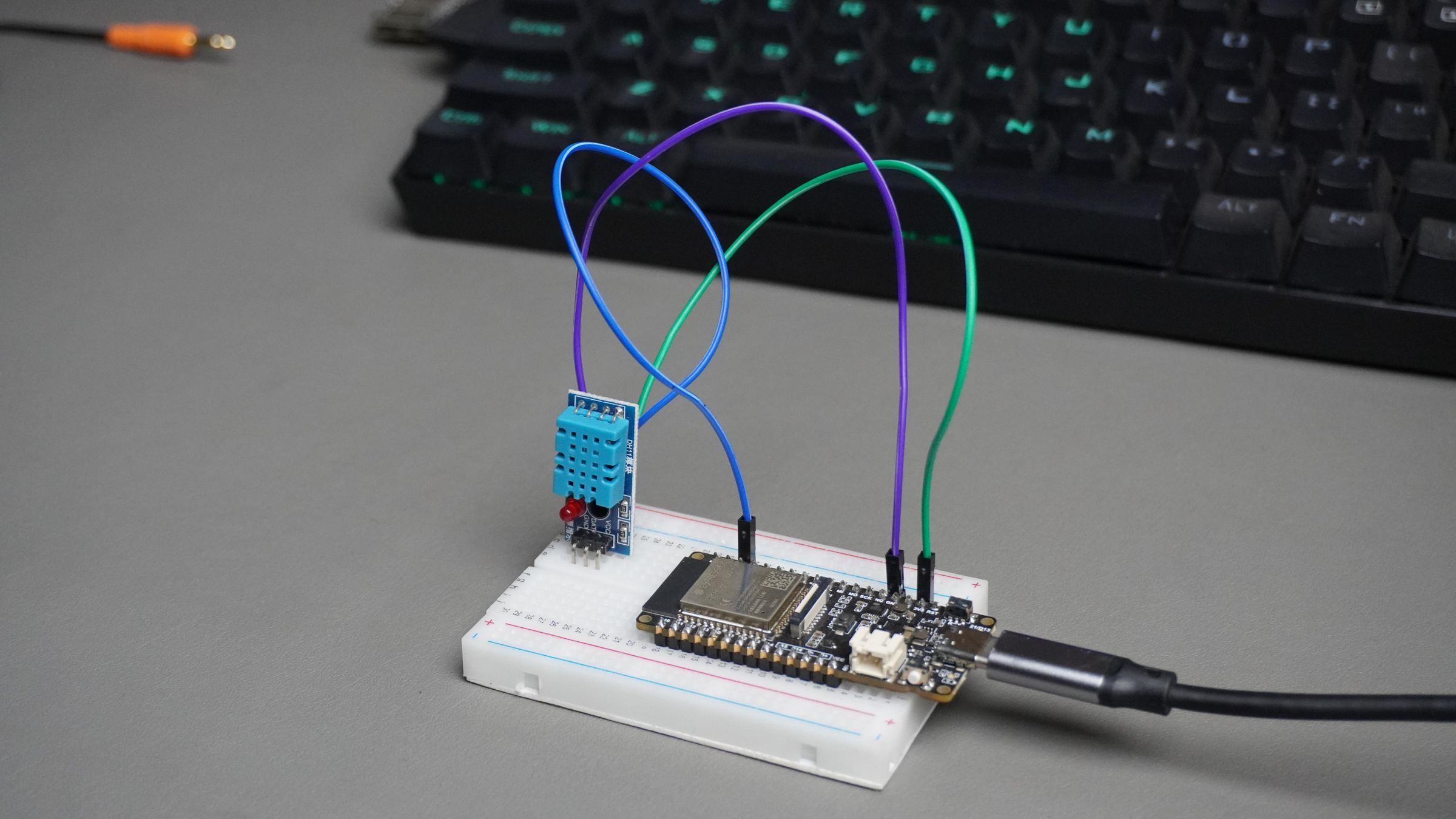
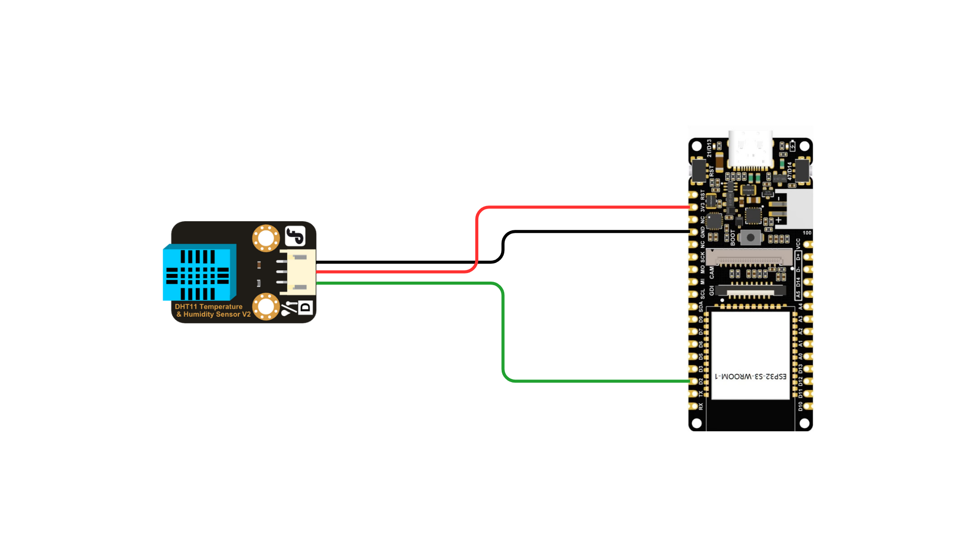 In this example, we use a DFRobot FireBeetle ESP32-S3, which has:
- An on-board LED connected to GPIO 21
- A DHT11 temperature & humidity sensor connected to GPIO 3
This sketch demonstrates how ESP32 exposes real hardware as MCP tools that an AI can call safely. What This Code Does (High Level)
- Connects the ESP32 to Wi-Fi
- Opens a WebSocket connection to the MCP server
Registers two MCP tools:
- room_light → Control the LED
- room_climate → Read temperature & humidity
- Waits for AI requests and executes them on real hardware
Required Libraries Make sure these libraries are installed in Arduino IDE:
#include  <WebSocketMCP.h>
#include  <ArduinoJson.h>
#include  <DHT11.h>
Wi-Fi Configuration
const  char\* WIFI\_SSID = "--------";
const  char\* WIFI\_PASS = "--------";
Replace these with your own Wi-Fi credentials. MCP Endpoint
const char\* MCP\_ENDPOINT = "wss://api.xiaozhi.me/mcp/?token=...";This is the secure WebSocket endpoint that connects your ESP32 to the AI. How to Get Your MCP Endpoint
- Go to xiaozhi.me
- Open Configure Role
- Scroll to MCP Settings
- Click Get MCP Endpoint
- Copy and paste it here
Hardware Configuration
#define LED\_PIN 21
#define DHT\_PIN 3- LED is connected to GPIO 21
- DHT11 data pin is connected to GPIO 3
MCP Tool 1: LED Control (room_light) Tool Definition:
mcp.registerTool(
"room\_light",
"Control LED connected to ESP32",
"{\\"type\\":\\"object\\",\\"properties\\":{\\"state\\":{\\"type\\":\\"string\\",\\"enum\\":\[\\"on\\",\\"off\\"\]}},\\"required\\":\[\\"state\\"\]}",
This tool:
- Is named room_light
- Accepts only one parameter
- state must be "on" or "off"
- No other values are allowed.
Tool Execution Logic
if (state == "on") {
	digitalWrite(LED\_PIN, HIGH);
} else  if (state == "off") {
	digitalWrite(LED\_PIN, LOW);
}- "on" → LED turns ON
- "off" → LED turns OFF
If the JSON is invalid or the value is wrong, an error is returned to the AI. Tool Response
{
"success": true,
"device": "LED",
"state": "on"
}
This response tells the AI exactly what happened.
MCP Tool 2: Climate Sensor (room_climate) Tool Definition:
mcp.registerTool(
	"room\_climate",
	"Read temperature and humidity from DHT11",
	"{\\"type\\":\\"object\\",\\"properties\\":{}}",
This tool:
- Takes no input
- Simply reads the DHT11 sensor
Sensor Reading
int result = dht11.readTemperatureHumidity(temperature, humidity);- If the read fails, an error is returned.
- If successful, temperature and humidity are sent back to the AI.
Tool Response Example
{
"success": true,
"temperature\_c": 28,
"humidity\_percent": 60
}
MCP Connection Callback void onMcpConnectionChange(bool connected) When MCP connects:
- Tools are registered
When MCP disconnects:
- Status is printed on Serial Monitor
This ensures tools are available only when MCP is active.
Setup Function In setup():
- Serial communication starts
- LED pin is configured
- Wi-Fi connection is established
- MCP client is started
mcp.begin(MCP\_ENDPOINT, onMcpConnectionChange);Loop Function
void loop() {
	mcp.loop();
}
This keeps the MCP connection alive and listens for AI tool calls.
How the Full Flow Works
- User speaks to AI
- AI selects an MCP tool
- AI sends structured JSON
- ESP32 validates input
- Hardware action is executed
- ESP32 sends response
- AI confirms result to user
Step 12: Google Calendar Demo (ESP32 + MCP)
 In this step, the ESP32 becomes a real Google Calendar assistant, not just a voice demo.
The same ESP32-S3 board runs:
In this step, the ESP32 becomes a real Google Calendar assistant, not just a voice demo.
The same ESP32-S3 board runs:
- MCP client (connected to Xiaozhi AI)
- Custom calendar tools (set_meeting, get_meetings)
- Google Calendar integration via Google Apps Script
When you speak a command, the AI decides which tool to call, and the ESP32 executes it.
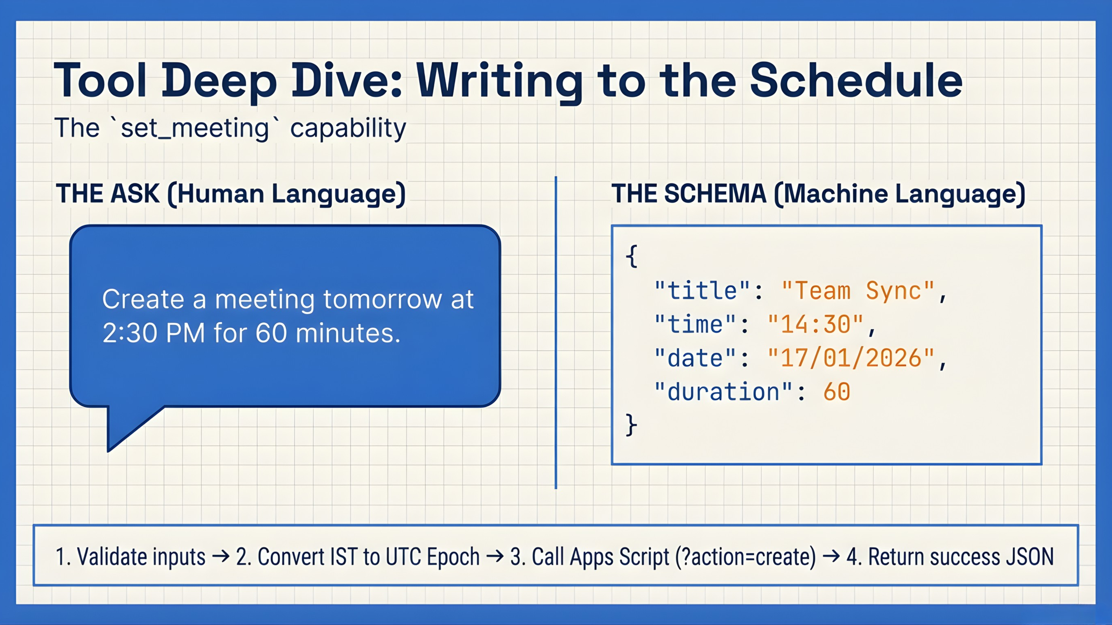 1. set_meeting – Create a Google Calendar Event
This function is used when the AI hears something like:
1. set_meeting – Create a Google Calendar Event
This function is used when the AI hears something like:
“Create a meeting tomorrow at 2:30 PM for 60 minutes”
- What the AI Sends to ESP32 (via MCP)
- The AI does not send epoch time.
It sends human-readable structured data:
{
"title": "Project Review",
"time": "14:30",
"date": "18/01/2026",
"duration": 60
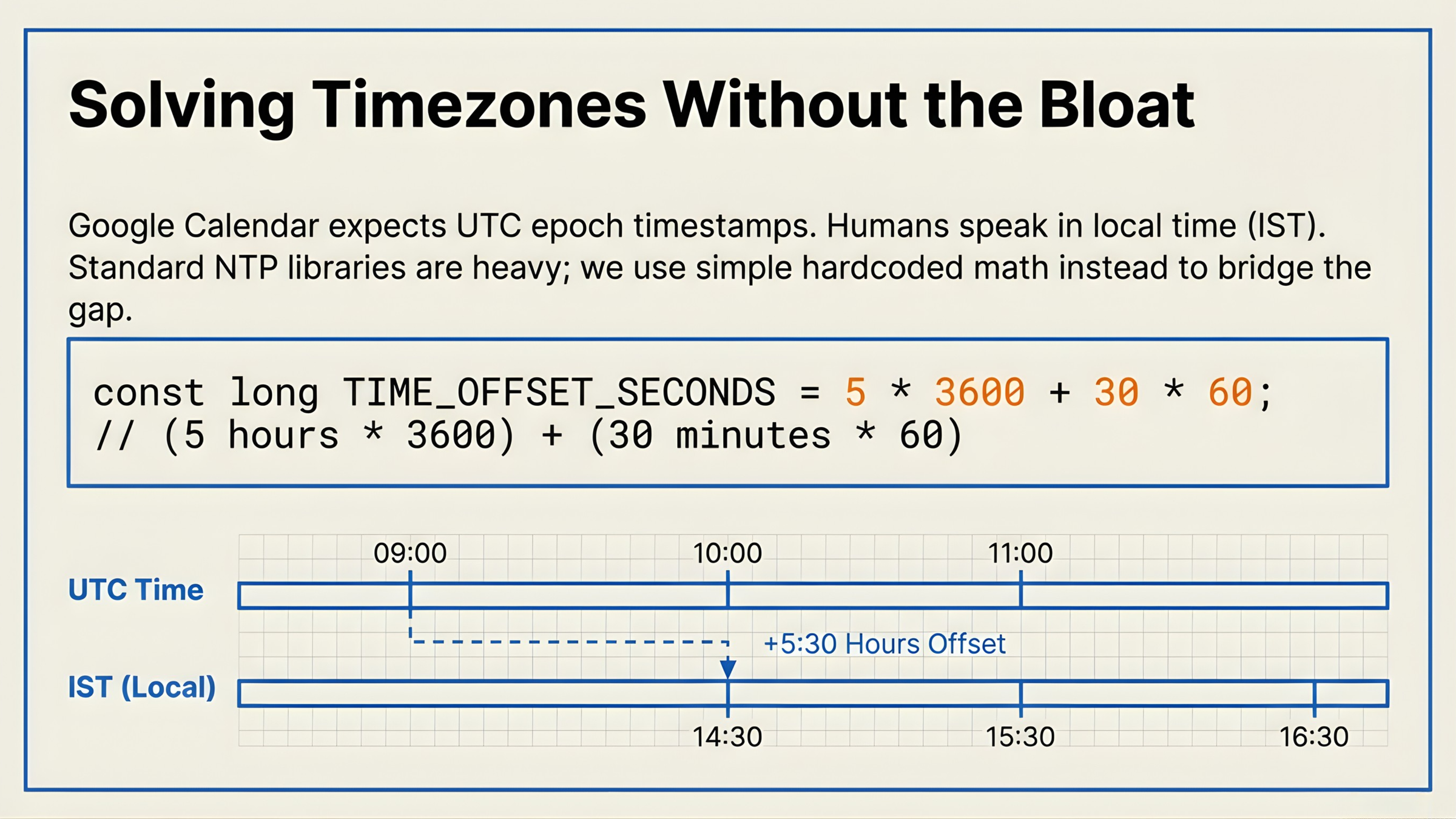
}This is important because LLMs are bad at time math.
What the ESP32 Does (Step-by-Step) 1. Validate Inputs
if (timeStr.length() == 0 || dateStr.length() == 0)- Ensures time and date are present.
2. Convert Time + Date → Epoch (IST → UTC)
long long epochMs = convertToEpochMs(timeStr, dateStr);Inside convertToEpochMs():
- Accepts multiple formats
- Builds a tm structure
- Assumes IST
- Converts to UTC epoch
- Returns milliseconds
This fixes the biggest AI scheduling bug.
3. Build HTTP Request
?action=create
&title=Project%20Review
&start\_epoch=1768636200000
&duration=30
The ESP32 sends this to Google Apps Script.
4. Google Apps Script Creates the Event
var start = new Date(startEpoch);
var end = new Date(start.getTime() + durationMin \* 60000);
CalendarApp.getDefaultCalendar().createEvent(
	title, start, end
);
Event is now live in Google Calendar. Response Back to AI
{
"success": true,
"meeting": "created",
"title": "Project Review",
"scheduled\_time": "14:30 IST",
"scheduled\_date": "18/01/2026"
}
AI speaks the confirmation.
2. get_meetings – Retrieve Calendar Events
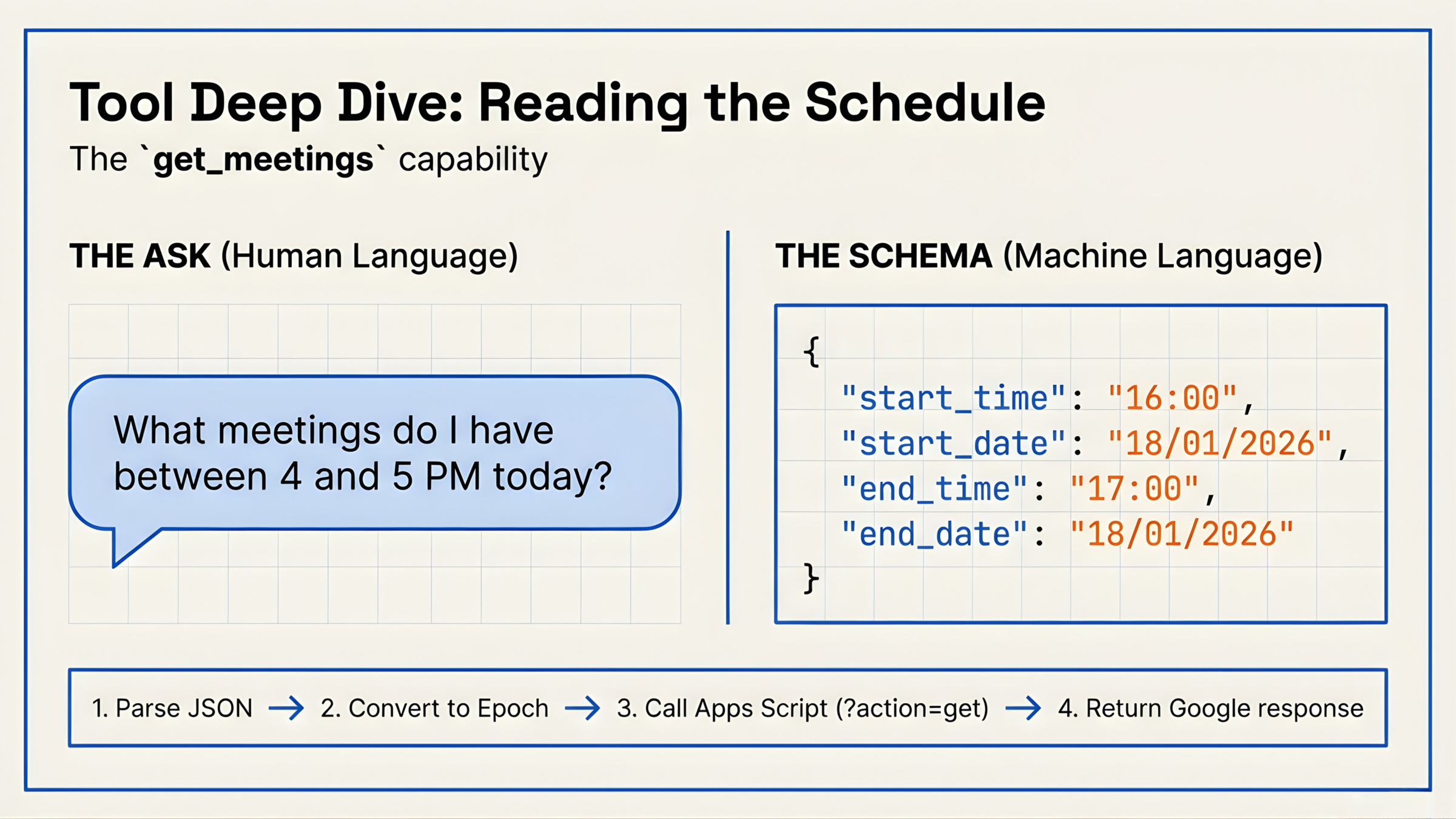
Used when the AI hears:
“What meetings do I have tomorrow evening from 4 to 5?”
What the AI Sends to ESP32
{
"start\_time": "16:00",
"start\_date": "18/01/2026",
"end\_time": "17:00",
"end\_date": "18/01/2026"
}
Again — no epoch from AI. What the ESP32 Does
1. Validate Time Range Checks all fields exist and:
startEpoch < endEpoch2. Convert Both Times to Epoch
startEpochMs = convertToEpochMs(start\_time, start\_date);
endEpochMs = convertToEpochMs(end\_time, end\_date);
Both are:
- Parsed as IST
- Converted to UTC
- Sent in milliseconds
3. Build Request
?action=get
&start\_epoch=1768636200000
&end\_epoch=1768643400000
Google Apps Script Fetches Meetings
var events = CalendarApp
	.getDefaultCalendar()
	.getEvents(startTime, endTime);
Each event is converted into JSON:
{
"title": "Project Review",
"start\_readable": "Sat Jan 18 2026 16:00:00 GMT+0530",
"end\_readable": "Sat Jan 18 2026 16:30:00 GMT+0530"
}
Response Back to ESP32 → AI
{
"success": true,
"count": 1,
"meetings": \[ ... \]
}
The AI can now:
- Read meetings aloud
- Summarize schedule
- Make decisions (free/busy logic)
Step 13: Get the Google Apps Script Web URL
To connect ESP32 with Google Calendar, we need a public Web App URL from Google Apps Script.
1. Create a New Script
- Go to https://script.google.com/
- Click New Project
- Delete the default code
- Copy–paste the provided Apps Script code
2. Save the Script
- Click Save
- Give the project a name (e.g., ESP32 Calendar MCP)
3. Deploy as Web App
- Click Deploy → New deployment
- Select Web app
Set the options:
- Execute as: Me
- Who has access: Anyone
- Then click Deploy
On first deploy, Google will ask for permission — approve it.
4. Copy the Web URL
- After deployment, Google shows a Web App URL
- Copy this URL
5. Paste URL in ESP32 Code
- Replace CALENDAR_URL in the ESP32 sketch:
const char\* CALENDAR\_URL = "PASTE\_YOUR\_WEB\_APP\_URL\_HERE";SCRIPT
function doGet(e) {
	var action = e.parameter.action || "create";

	if (action === "create") {
		return createMeeting(e);
	} else if (action === "get") {
		return getMeetings(e);
	}

	return ContentService.createTextOutput(JSON.stringify({
		success: false,
		error: "Invalid action. Use action=create or action=get"
	})).setMimeType(ContentService.MimeType.JSON);
}

// Create meeting function
function createMeeting(e) {
	var title = e.parameter.title || "ESP32 Meeting";
	var startEpoch = Number(e.parameter.start_epoch);
	var durationMin = Number(e.parameter.duration || 30);

	if (!startEpoch || isNaN(startEpoch)) {
		return ContentService.createTextOutput(JSON.stringify({
		success: false,
		error: "Invalid epoch"
	})).setMimeType(ContentService.MimeType.JSON);
}

var start = new Date(startEpoch);
var end = new Date(start.getTime() + durationMin * 60000);

try {
	var event = CalendarApp.getDefaultCalendar().createEvent(
	title,
	start,
	end,
	{ description: "Created from ESP32" }
	);

	return ContentService
		.createTextOutput(JSON.stringify({
		success: true,
		message: "Meeting created",
		title: title,
		start: start.toString(),
		end: end.toString(),
		id: event.getId()
	}))
	.setMimeType(ContentService.MimeType.JSON);
} catch (error) {
		return ContentService
			.createTextOutput(JSON.stringify({
			success: false,
			error: error.toString()
		}))
		.setMimeType(ContentService.MimeType.JSON);
	}
}

// Get meetings function
function getMeetings(e) {
	var startEpoch = Number(e.parameter.start_epoch);
	var endEpoch = Number(e.parameter.end_epoch);

	if (!startEpoch || !endEpoch || isNaN(startEpoch) || isNaN(endEpoch)) {
		return ContentService.createTextOutput(JSON.stringify({
			success: false,
			error: "Invalid start_epoch or end_epoch"
		})).setMimeType(ContentService.MimeType.JSON);
	}

try {
var startTime = new Date(startEpoch);
var endTime = new Date(endEpoch);

var events = CalendarApp.getDefaultCalendar().getEvents(startTime, endTime);

var meetings = events.map(function(event) {
	return {
		title: event.getTitle(),
		start: event.getStartTime().getTime(),
		end: event.getEndTime().getTime(),
		start_readable: event.getStartTime().toString(),
		end_readable: event.getEndTime().toString(),
		description: event.getDescription() || "",
		location: event.getLocation() || ""
	};
});

return ContentService
	.createTextOutput(JSON.stringify({
		success: true,
		count: meetings.length,
		search_range: {
		start: startTime.toString(),
		end: endTime.toString()
	},
	meetings: meetings
	}))
	.setMimeType(ContentService.MimeType.JSON);
	} catch (error) {
	return ContentService
		.createTextOutput(JSON.stringify({
			success: false,
			error: error.toString()
		}))
		.setMimeType(ContentService.MimeType.JSON);
	}
}
Step 14: Xiaozhi MCP Light (Relay Example)
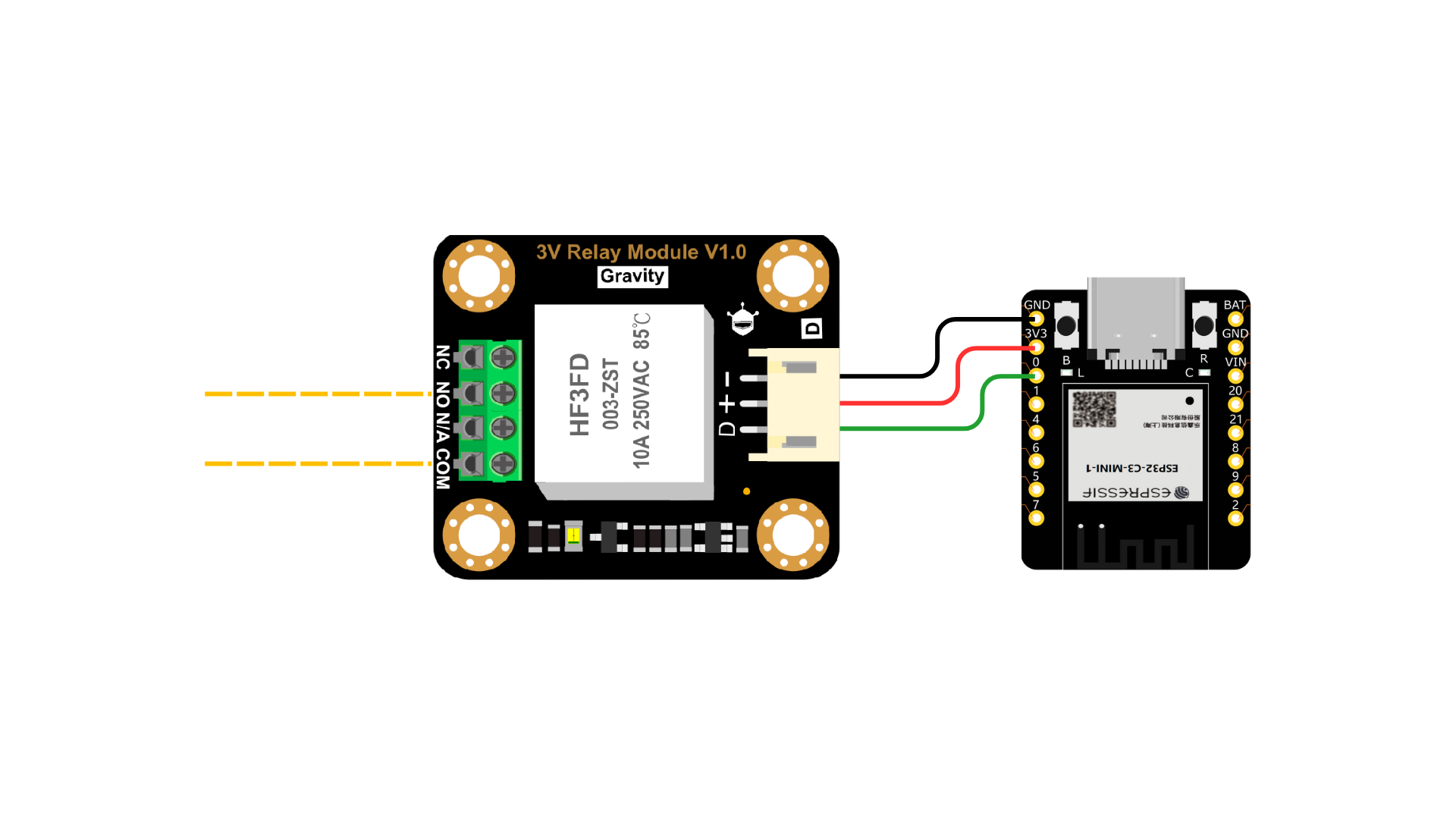
- In this step, we demonstrate real AI-controlled hardware execution using Xiaozhi MCP.
- Instead of a camera board, we use a DFRobot Beetle ESP32-C3, connected to a 10A relay module on GPIO 0.
- This relay can control real loads like lights, fans, or appliances.
- This example proves that MCP is not limited to one ESP32 — multiple ESP32 devices can expose tools independently.
Hardware Used:
- DFRobot Beetle ESP32-C3
- 10A Relay Module
- Relay control pin → GPIO 0
When the relay pin goes HIGH, the relay turns ON. When it goes LOW, the relay turns OFF.
What This Example Does The ESP32 exposes a single MCP tool: office_light This tool allows the AI to:
- Turn the relay ON
- Turn the relay OFF
The AI does not toggle GPIOs directly. It calls a structured tool, and the ESP32 executes it safely.
How the MCP Flow Works?
1.Voice or AI Command Example:
“Turn on the office light”
2. Xiaozhi AI
- Understands intent
- Calls the MCP tool office_light
- Sends structured JSON: { "state": "on" }
3. ESP32 Execution
- Receives the tool call
- Sets GPIO 0 HIGH or LOW
- Controls the relay instantly
4. Response Back to AI
- ESP32 sends execution status
- AI confirms the action
- This is true AI → hardware control, not keywords or if-else logic.
Conclusion
 In this project, we built a real voice-controlled AI system on ESP32 — not a chatbot, but an execution engine.
Using MCP (Model Context Protocol), the ESP32 exposes its hardware and services as structured tools that an AI can safely call. This allowed us to:
In this project, we built a real voice-controlled AI system on ESP32 — not a chatbot, but an execution engine.
Using MCP (Model Context Protocol), the ESP32 exposes its hardware and services as structured tools that an AI can safely call. This allowed us to:
- Control real hardware (LEDs, sensors, relays)
- Convert natural language into deterministic actions
- Create and fetch Google Calendar meetings
- Handle time, timezone, and epoch conversion directly on the device
What you’ve seen in this project are just a few examples of what MCP enables. The real power is that any hardware or software capability can be exposed as an MCP tool — from home automation and factory sensors to cloud services, dashboards, and industrial control systems. The possibilities are truly endless when AI is combined with structured, secure execution. The key takeaway is the architecture:
- The AI decides what needs to be done
- MCP defines how it can be done
- ESP32 executes it safely in the real world
If you understand this flow, you’re no longer just building IoT projects — you’re designing AI-driven automation systems.
Special Thanks A big thank you to DFRobot for providing all the hardware components used in this project and supporting open, educational innovation.
Happy building 🚀
Discussion
No comments yet
Be the first to share your feedback or ask a question about this project.